Page 1758 of 3342
B: DISASSEMBLY AND ASSEMBLY
1. COMBINATION SWITCH
Refer to 6-2 [W4C1] as for disassembly and assembly of
combination switch.
C: INSPECTION
1. COMBINATION SWITCH (ON-CAR)
1) Remove instrument panel lower cover.
2) Remove lower column cover.
B6M0238
3) Unfasten holddown clip which secures harness, and
disconnect connectors from body harness.
4) Move combination switch to respective positions and
check continuity between terminals as indicated in table
below:
Turn signal switch
Terminal
Switch positiona-5 a-7 a-6
TurnL⋅L′��
*xx
N
*xx
R⋅R′��
B6M0344
2. HAZARD SWITCH
Move hazard switch to each position and check continuity
between terminals as indicated in table below:
73910561 2
ON��
�����
OFF����
20
6-2SERVICE PROCEDURE
6. Turn Signal and Hazard Warning Light
Page 1759 of 3342
![SUBARU LEGACY 1997 Service Repair Manual 7. Back-up Light
A: REMOVAL AND INSTALLATION
1. BACK-UP LIGHT
Refer to 6-2 [W5A2] as for removal and installation of rear
finisher.
2. BACK-UP LIGHT SWITCH (MT MODEL)
Refer to 3-1 [W2B1 (AWD) or W3A0](/manual-img/17/57434/w960_57434-1758.png "SUBARU LEGACY 1997 Service Repair Manual 7. Back-up Light
A: REMOVAL AND INSTALLATION
1. BACK-UP LIGHT
Refer to 6-2 [W5A2] as for removal and installation of rear
finisher.
2. BACK-UP LIGHT SWITCH (MT MODEL)
Refer to 3-1 [W2B1 (AWD) or W3A0")
7. Back-up Light
A: REMOVAL AND INSTALLATION
1. BACK-UP LIGHT
Refer to 6-2 [W5A2] as for removal and installation of rear
finisher.
2. BACK-UP LIGHT SWITCH (MT MODEL)
Refer to 3-1 [W2B1 (AWD) or W3A0 (FWD)] as for removal
and installation of back-up light switch.
3. INHIBITOR SWITCH (AT MODEL)
Refer to 3-2 [W4A4] as for removal and installation of
inhibitor switch (R position switch).
B: INSPECTION
1. INHIBITOR SWITCH (AT MODEL)
Refer to 3-2 [W2B2] as for inspection of inhibitor switch.
B6M0068
8. Room Light and Door Switch
A: REMOVAL AND INSTALLATION
1. ROOM LIGHT
1) Pry room light lens off using a screwdriver.
2) Remove screws which secure room light body.
3) Remove room light body while disconnecting connector.
B6M0345A
2. TRUNK ROOM LIGHT (SEDAN)
1) Turn trunk room light body by hand and remove it from
rear shelf panel.
2) Disconnect connector of trunk room light.
B6M0069
3. LUGGAGE ROOM LIGHT (WAGON)
1) Pry luggage room light lens off using a screwdriver.
2) Remove screws which secure luggage room light body.
3) Remove luggage room light body while disconnecting
connector.
21
6-2SERVICE PROCEDURE
7. Back-up Light - 8. Room Light and Door Switch
Page 1760 of 3342
![SUBARU LEGACY 1997 Service Repair Manual 7. Back-up Light
A: REMOVAL AND INSTALLATION
1. BACK-UP LIGHT
Refer to 6-2 [W5A2] as for removal and installation of rear
finisher.
2. BACK-UP LIGHT SWITCH (MT MODEL)
Refer to 3-1 [W2B1 (AWD) or W3A0](/manual-img/17/57434/w960_57434-1759.png "SUBARU LEGACY 1997 Service Repair Manual 7. Back-up Light
A: REMOVAL AND INSTALLATION
1. BACK-UP LIGHT
Refer to 6-2 [W5A2] as for removal and installation of rear
finisher.
2. BACK-UP LIGHT SWITCH (MT MODEL)
Refer to 3-1 [W2B1 (AWD) or W3A0")
7. Back-up Light
A: REMOVAL AND INSTALLATION
1. BACK-UP LIGHT
Refer to 6-2 [W5A2] as for removal and installation of rear
finisher.
2. BACK-UP LIGHT SWITCH (MT MODEL)
Refer to 3-1 [W2B1 (AWD) or W3A0 (FWD)] as for removal
and installation of back-up light switch.
3. INHIBITOR SWITCH (AT MODEL)
Refer to 3-2 [W4A4] as for removal and installation of
inhibitor switch (R position switch).
B: INSPECTION
1. INHIBITOR SWITCH (AT MODEL)
Refer to 3-2 [W2B2] as for inspection of inhibitor switch.
B6M0068
8. Room Light and Door Switch
A: REMOVAL AND INSTALLATION
1. ROOM LIGHT
1) Pry room light lens off using a screwdriver.
2) Remove screws which secure room light body.
3) Remove room light body while disconnecting connector.
B6M0345A
2. TRUNK ROOM LIGHT (SEDAN)
1) Turn trunk room light body by hand and remove it from
rear shelf panel.
2) Disconnect connector of trunk room light.
B6M0069
3. LUGGAGE ROOM LIGHT (WAGON)
1) Pry luggage room light lens off using a screwdriver.
2) Remove screws which secure luggage room light body.
3) Remove luggage room light body while disconnecting
connector.
21
6-2SERVICE PROCEDURE
7. Back-up Light - 8. Room Light and Door Switch
Page 1761 of 3342
 Remove rubber boot of door switch.
2) Remove screw which secures door switch to body.
3) Remove door switch while disconnecting connector.
5. TRUNK ROOM LIGHT SWITCH (SEDAN)")
B6M0070A
4. DOOR SWITCH
1) Remove rubber boot of door switch.
2) Remove screw which secures door switch to body.
3) Remove door switch while disconnecting connector.
5. TRUNK ROOM LIGHT SWITCH (SEDAN)
Refer to 5-1 [W2A3] as for removal and installation of trunk
room light switch which is installed in trunk lid lock.
6. LUGGAGE ROOM LIGHT SWITCH (WAGON)
Refer to 5-2 [W3A2] as for removal and installation of lug-
gage room light switch which is installed in rear gate lock.
B6M0071
B: INSPECTION
1. DOOR SWITCH
Move switch and check continuity between terminal of door
switch and switch body.
Switch position Terminal Switch body
Open (ON)��
Push in (OFF)
B6M0072A
2. TRUNK ROOM LIGHT SWITCH (SEDAN)
Move switch and check continuity between terminals of
trunk room light switch.
Terminal
Switch position12
Open (ON)��
Push in (OFF)
B6M0073A
3. LUGGAGE ROOM LIGHT SWITCH (WAGON)
Move switch and check continuity between terminals of
luggage room light switch.
Terminal
Switch position12
Open (ON)��
Push in (OFF)
22
6-2SERVICE PROCEDURE
8. Room Light and Door Switch
Page 1762 of 3342
 Pry spot light lens off using a screwdriver.
2) Remove screws which secure spot light body.
3) Remove spot light body whil")
B6M0346
9. Spot Light
A: REMOVAL AND INSTALLATION
1. SPOT LIGHT AND SWITCH
1) Pry spot light lens off using a screwdriver.
2) Remove screws which secure spot light body.
3) Remove spot light body while disconnecting connec-
tor(s).
B6M0347
B: INSPECTION
1. SPOT LIGHT SWITCH
Move switch and check continuity between terminal of spot
light switch connector and steel plate as shown.
Switch position Connector terminal Plate
Open (OFF)
Push in (ON)��
B6M0907A
10. Front Wiper and Washer
A: ON-CAR SERVICES
1. ADJUSTMENT
1) Turn the wiper switch to OFF position.
2) Adjust blades in original position as shown in figure by
changing wiper arm installation.
G6M0116
3) Stop the vehicle.
4) Adjust washer ejecting point on windshield glass as
shown in figure.
Ejecting point:
A: 375 mm (14.76 in)
B: 150 mm (5.91 in)
C: 380 mm (14.96 in)
B6M0107A
B: REMOVAL AND INSTALLATION
1. BLADE
Pull out blade following the arrow direction from arm while
pushing up locking clip.
23
6-2SERVICE PROCEDURE
9. Spot Light - 10. Front Wiper and Washer
Page 1763 of 3342
 Pry spot light lens off using a screwdriver.
2) Remove screws which secure spot light body.
3) Remove spot light body whil")
B6M0346
9. Spot Light
A: REMOVAL AND INSTALLATION
1. SPOT LIGHT AND SWITCH
1) Pry spot light lens off using a screwdriver.
2) Remove screws which secure spot light body.
3) Remove spot light body while disconnecting connec-
tor(s).
B6M0347
B: INSPECTION
1. SPOT LIGHT SWITCH
Move switch and check continuity between terminal of spot
light switch connector and steel plate as shown.
Switch position Connector terminal Plate
Open (OFF)
Push in (ON)��
B6M0907A
10. Front Wiper and Washer
A: ON-CAR SERVICES
1. ADJUSTMENT
1) Turn the wiper switch to OFF position.
2) Adjust blades in original position as shown in figure by
changing wiper arm installation.
G6M0116
3) Stop the vehicle.
4) Adjust washer ejecting point on windshield glass as
shown in figure.
Ejecting point:
A: 375 mm (14.76 in)
B: 150 mm (5.91 in)
C: 380 mm (14.96 in)
B6M0107A
B: REMOVAL AND INSTALLATION
1. BLADE
Pull out blade following the arrow direction from arm while
pushing up locking clip.
23
6-2SERVICE PROCEDURE
9. Spot Light - 10. Front Wiper and Washer
Page 1776 of 3342
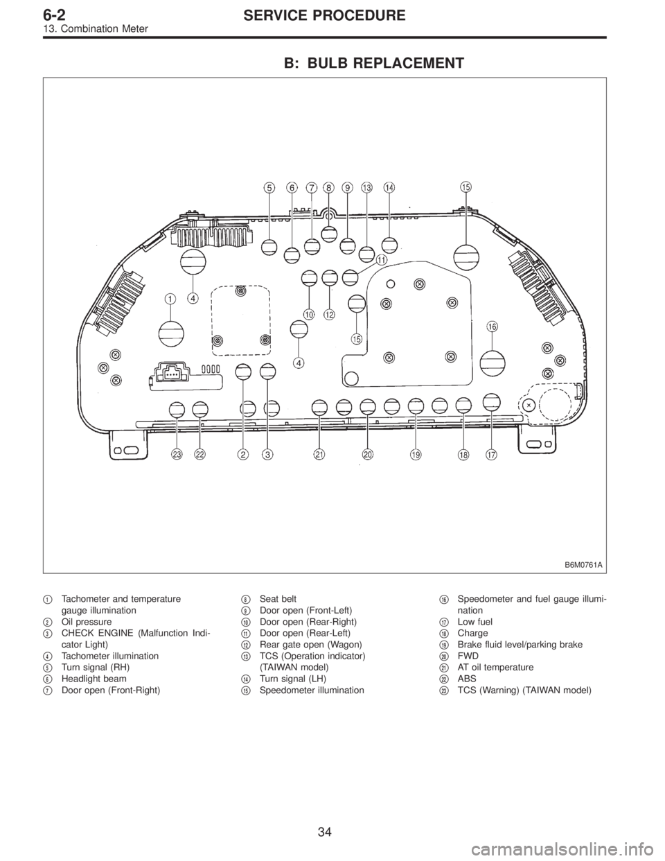
B: BULB REPLACEMENT
B6M0761A
�1Tachometer and temperature
gauge illumination
�
2Oil pressure
�
3CHECK ENGINE (Malfunction Indi-
cator Light)
�
4Tachometer illumination
�
5Turn signal (RH)
�
6Headlight beam
�
7Door open (Front-Right)�
8Seat belt
�
9Door open (Front-Left)
�
10Door open (Rear-Right)
�
11Door open (Rear-Left)
�
12Rear gate open (Wagon)
�
13TCS (Operation indicator)
(TAIWAN model)
�
14Turn signal (LH)
�
15Speedometer illumination�
16Speedometer and fuel gauge illumi-
nation
�
17Low fuel
�
18Charge
�
19Brake fluid level/parking brake
�
20FWD
�
21AT oil temperature
�
22ABS
�
23TCS (Warning) (TAIWAN model)
34
6-2SERVICE PROCEDURE
13. Combination Meter
Page 1779 of 3342
 Open the engine hood.
2) Disconnect connector of horn.
3) Remove the horn.
Tightening torque:
18±5 N⋅m (1.8±0.5 kg-m,")
B6M0349
15. Horn and Cigarette Lighter
A: REMOVAL AND INSTALLATION
1. HORN
1) Open the engine hood.
2) Disconnect connector of horn.
3) Remove the horn.
Tightening torque:
18±5 N⋅m (1.8±0.5 kg-m, 13.0±3.6 ft-lb)
CAUTION:
After installing horn, connect connector, fit firmly wir-
ing harness to prevent from disconnecting due to
vibration.
B6M0124
2. HORN SWITCH (HORN PAD)
1) Remove screw which secures horn switch (steering
pad) to the base of steering wheel.
2) Remove horn switch (steering pad) from steering wheel
while disconnecting connector.
B6M0350A
3. CIGARETTE LIGHTER
1) Remove center panel from instrument panel.
5-4 [W1A0].>
2) Disconnect connector from cigarette lighter.
3) Turn illumination socket 45°counterclockwise and
remove it.
4) Loosen nut, and then remove cigarette lighter body.
CAUTION:
�Align socket with cutout portion of instrument panel
during installation.
�In case of replacing cigarette lighter, use genuine
part only and always replace both plug and socket
combination.
37
6-2SERVICE PROCEDURE
15. Horn and Cigarette Lighter
![SUBARU LEGACY 1997 Service Repair Manual B: DISASSEMBLY AND ASSEMBLY
1. COMBINATION SWITCH
Refer to 6-2 [W4C1] as for disassembly and assembly of
combination switch.
C: INSPECTION
1. COMBINATION SWITCH (ON-CAR)
1) Remove instrument panel low](/manual-img/17/57434/w960_57434-1757.png "SUBARU LEGACY 1997 Service Repair Manual B: DISASSEMBLY AND ASSEMBLY
1. COMBINATION SWITCH
Refer to 6-2 [W4C1] as for disassembly and assembly of
combination switch.
C: INSPECTION
1. COMBINATION SWITCH (ON-CAR)
1) Remove instrument panel low")