Page 1841 of 3342
G: DIAGNOSTICS PROCEDURE FOR DOOR
SWITCH SIGNAL
1. Check door switch input signal for security
control module.
Not OK
�OK
Go to next step on basic diagnostics procedure.
2. Check door switch.
OK
�Not OK
Replace door switch.
Repair or replace wiring harness between door
switch and security control module.
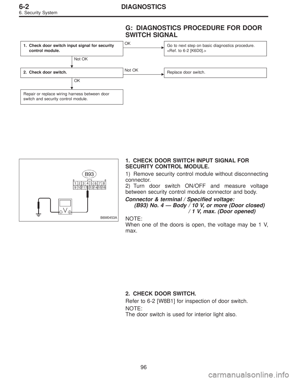
B6M0453A
1. CHECK DOOR SWITCH INPUT SIGNAL FOR
SECURITY CONTROL MODULE.
1) Remove security control module without disconnecting
connector.
2) Turn door switch ON/OFF and measure voltage
between security control module connector and body.
Connector & terminal / Specified voltage:
(B93) No. 4—Body / 10 V, or more (Door closed)
/ 1 V, max. (Door opened)
NOTE:
When one of the doors is open, the voltage may be 1 V,
max.
2. CHECK DOOR SWITCH.
Refer to 6-2 [W8B1] for inspection of door switch.
NOTE:
The door switch is used for interior light also.
�
�
96
6-2DIAGNOSTICS
6. Security System
Page 1843 of 3342
 OR REAR GATE
SWITCH (WAGON) SIGNAL
1. Check trunk lid switch (SEDAN) or rear gate
switch (WAGON) input signal for security
control module.
Not OK")
I: DIAGNOSTICS PROCEDURE FOR TRUNK
LID SWITCH (SEDAN) OR REAR GATE
SWITCH (WAGON) SIGNAL
1. Check trunk lid switch (SEDAN) or rear gate
switch (WAGON) input signal for security
control module.
Not OK
�OK
Go to next step on basic diagnostics procedure.
2. Check trunk lid switch (SEDAN) or rear gate
switch (WAGON).
OK
�Not OK
Replace trunk lid switch (or rear gate switch).
Repair or replace wiring harness between trunk lid
switch (or rear gate switch) and security control
module.
B6M0450A
1. CHECK TRUNK LID SWITCH (SEDAN) OR REAR
GATE SWITCH (WAGON) INPUT SIGNAL FOR
SECURITY CONTROL MODULE.
1) Remove security control module without disconnecting
connector.
2) Turn trunk lid switch (or rear gate switch) ON/OFF and
measure voltage between security control module connec-
tor and body.
Connector & terminal / Specified voltage:
(B93) No. 11—Body / 10 V, or more
(Lid or gate closed)
/ 1 V, max.
(Lid or gate opened)
2. CHECK TRUNK LID SWITCH (SEDAN) OR REAR
GATE SWITCH (WAGON).
Refer to 6-2 [W8B2/W8B3] for inspection of trunk lid switch/
rear gate switch.
NOTE:
The trunk lid switch/rear gate switch is used for both trunk
room light/luggage room light.
�
�
98
6-2DIAGNOSTICS
6. Security System
Page 1851 of 3342

N: DIAGNOSTICS PROCEDURE FOR
HEADLIGHT ALARM SIGNAL
1. Check headlight alarm output signal for security
control module.
Not OK
�OK
5. Check headlight alarm relay.
OK Not OK
Repair or replace
wiring harness of
headlight circuit.
Replace headlight
alarm relay.
2. Check power supply for headlight alarm relay.
OK
�Not OK
Repair or replace wiring harness between
headlight alarm relay and battery.
3. Check continuity of headlight alarm relay.
OK
�Not OK
Replace headlight alarm relay.
4. Check harness connector between headlight
alarm relay and security control module.
OK
�Not OK
Repair or replace wiring harness between
headlight alarm relay and security control
module.
Replace security control module.
B6M0457A
1. CHECK HEADLIGHT ALARM OUTPUT SIGNAL
FOR SECURITY CONTROL MODULE.
1) Remove security control module without disconnecting
connector.
2) Measure voltage between security control module con-
nector and body.
Connector & terminal / Specified voltage:
(B93) No. 12—Body / 10 V, or more
3) Set security system in armed state.
4) Open the door without ignition key to operate the secu-
rity system (alarm state).
5) Measure voltage between security control module and
body during alarm state.
Connector & terminal / Specified voltage:
(B93) No. 12—Body / repeats 1 V, max. (0.2 sec.)
and 10 V, or more (0.6 sec.)
intervals
��
�
�
�
�
106
6-2DIAGNOSTICS
6. Security System
Page 1852 of 3342
B6M0508A
2. CHECK POWER SUPPLY FOR HEADLIGHT ALARM
RELAY.
1) Remove headlight alarm relay without disconnecting
connector.
2) Measure voltage between headlight alarm relay con-
nector and body.
Connector & terminal / Specified voltage:
(B58) No. 1—Body / 10 V, or more
B6M0455A
3. CHECK CONTINUITY OF HEADLIGHT ALARM
RELAY.
1) Remove headlight alarm relay.
2) Check continuity between terminals No. 1 and No. 2 of
headlight alarm relay.
B6M0502A
4. CHECK HARNESS CONNECTOR BETWEEN
HEADLIGHT ALARM RELAY AND SECURITY
CONTROL MODULE.
1) Disconnect connectors of headlight alarm relay and
security control module.
2) Measure resistance of harness connector between
headlight alarm relay and security control module.
Connector & terminal / Specified resistance:
(B58) No. 2—(B93) No. 12 / 10Ω, max.
5. CHECK HEADLIGHT ALARM RELAY.
Refer to 6-2 [W22B2] for inspection of headlight alarm
relay.
107
6-2DIAGNOSTICS
6. Security System
Page 1877 of 3342
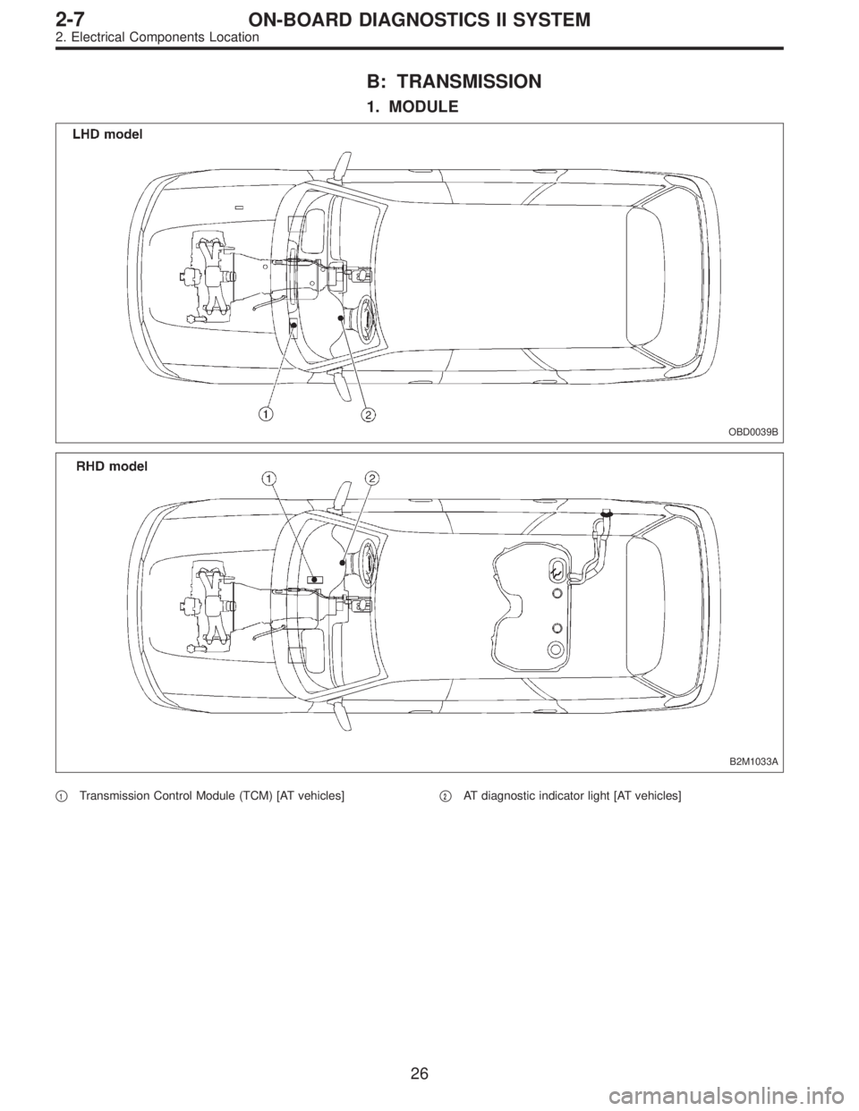
B: TRANSMISSION
1. MODULE
OBD0039B
B2M1033A
�1Transmission Control Module (TCM) [AT vehicles]�2AT diagnostic indicator light [AT vehicles]
26
2-7ON-BOARD DIAGNOSTICS II SYSTEM
2. Electrical Components Location
Page 1879 of 3342
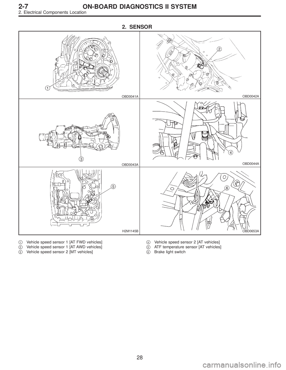
2. SENSOR
OBD0041AOBD0042A
OBD0043AOBD0044A
H2M1145BOBD0653A
�1Vehicle speed sensor 1 [AT FWD vehicles]
�
2Vehicle speed sensor 1 [AT AWD vehicles]
�
3Vehicle speed sensor 2 [MT vehicles]�
4Vehicle speed sensor 2 [AT vehicles]
�
5ATF temperature sensor [AT vehicles]
�
6Brake light switch
28
2-7ON-BOARD DIAGNOSTICS II SYSTEM
2. Electrical Components Location
Page 1882 of 3342
B2M0470C
3. Diagnosis System
A: CHECK ENGINE MALFUNCTION
INDICATOR LAMP (MIL)
1. ACTIVATION OF CHECK ENGINE MALFUNCTION
INDICATOR LAMP (MIL)
1) When ignition switch is turned to ON (engine off), the
CHECK ENGINE malfunction indicator lamp (MIL) in the
combination meter illuminates.
NOTE:
If the MIL does not illuminate, perform diagnostics of the
CHECK ENGINE light circuit or the combination meter cir-
cuit.
OBD0053A
2) After starting the engine, the MIL goes out. If it does not,
either the engine or the emission control system is mal-
functioning.
OBD0054A
3) If the diagnosis system senses a misfire which could
damage the catalyzer, the MIL will blink at a cycle of 1 Hz.
OBD0055A
4) When ignition switch is turned to ON (engine off) or to
“START” with the test mode connector connected, the MIL
blinks at a cycle of 3 Hz.
31
2-7ON-BOARD DIAGNOSTICS II SYSTEM
3. Diagnosis System
Page 1896 of 3342
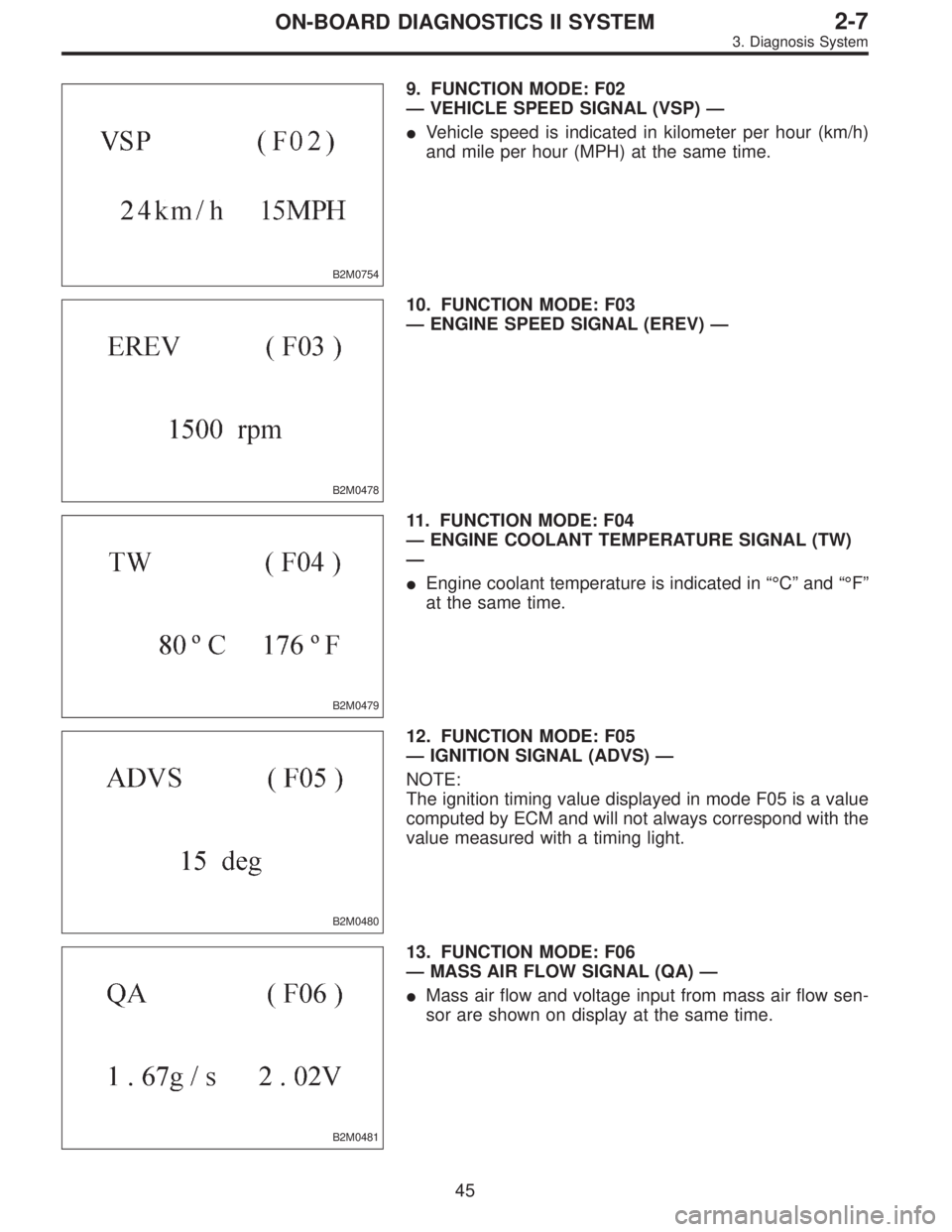
B2M0754
9. FUNCTION MODE: F02
—VEHICLE SPEED SIGNAL (VSP)—
�Vehicle speed is indicated in kilometer per hour (km/h)
and mile per hour (MPH) at the same time.
B2M0478
10. FUNCTION MODE: F03
—ENGINE SPEED SIGNAL (EREV)—
B2M0479
11. FUNCTION MODE: F04
—ENGINE COOLANT TEMPERATURE SIGNAL (TW)
—
�Engine coolant temperature is indicated in“°C”and“°F”
at the same time.
B2M0480
12. FUNCTION MODE: F05
—IGNITION SIGNAL (ADVS)—
NOTE:
The ignition timing value displayed in mode F05 is a value
computed by ECM and will not always correspond with the
value measured with a timing light.
B2M0481
13. FUNCTION MODE: F06
—MASS AIR FLOW SIGNAL (QA)—
�Mass air flow and voltage input from mass air flow sen-
sor are shown on display at the same time.
45
2-7ON-BOARD DIAGNOSTICS II SYSTEM
3. Diagnosis System
 Remove headlight alarm relay without disconnecting
connector.
2) Measure voltage between headlight alarm relay con-
nector and body.
Connec")

1. ACTIVATION OF CHECK ENGINE MALFUNCTION
INDICATOR LAMP (MIL)
1) When ignition switch is turned to ON (engine off), the
C")