Page 1780 of 3342
 Burned or shorted contacts
2) Broken or weak spring
3) Damaged harness
4) Worn or corroded mating surface of")
B: INSPECTION
1. HORN SWITCH
Ensure that horn switch is free from the following defects:
1) Burned or shorted contacts
2) Broken or weak spring
3) Damaged harness
4) Worn or corroded mating surface of horn plate
B6M0126A
2. HORN RELAY
Check continuity between terminals as indicated in table
below, when connecting the battery to terminals No. 1 and
No. 2.
When current flows. Between terminals
No. 2 and No. 3Continuity exists.
When current does not flow. Between terminals
No. 2 and No. 3Continuity does not
exist.
Between terminals
No. 1 and No. 2Continuity exists.
B6M0127
3. HORN
Make sure that horn sounds when battery voltage is
applied between connector terminal and horn body.
4. CIGARETTE LIGHTER
1) Remove plug. Then, check element’s contact for wear,
and element for accumulation of ashes, foreign particles,
etc.
2) Check element for discontinuity.
3) Remove socket and clean element. Then, check for
wear or foreign particles on element’s contact and mating
surface.
4) Ensure that cigarette lighter returns within 20 seconds
after it is turned to ON.
16. Power Window
A: REMOVAL AND INSTALLATION
1. MAIN SWITCH, SUB SWITCH AND POWER
WINDOW MOTOR
Refer to 5-2 [W2A2] as for removal and installation of
power window main switch, sub switch and motor.
NOTE:
To remove the power window motor, it is necessary to dis-
assemble the door component parts.
38
6-2SERVICE PROCEDURE
15. Horn and Cigarette Lighter - 16. Power Window
Page 1781 of 3342
 Burned or shorted contacts
2) Broken or weak spring
3) Damaged harness
4) Worn or corroded mating surface of")
B: INSPECTION
1. HORN SWITCH
Ensure that horn switch is free from the following defects:
1) Burned or shorted contacts
2) Broken or weak spring
3) Damaged harness
4) Worn or corroded mating surface of horn plate
B6M0126A
2. HORN RELAY
Check continuity between terminals as indicated in table
below, when connecting the battery to terminals No. 1 and
No. 2.
When current flows. Between terminals
No. 2 and No. 3Continuity exists.
When current does not flow. Between terminals
No. 2 and No. 3Continuity does not
exist.
Between terminals
No. 1 and No. 2Continuity exists.
B6M0127
3. HORN
Make sure that horn sounds when battery voltage is
applied between connector terminal and horn body.
4. CIGARETTE LIGHTER
1) Remove plug. Then, check element’s contact for wear,
and element for accumulation of ashes, foreign particles,
etc.
2) Check element for discontinuity.
3) Remove socket and clean element. Then, check for
wear or foreign particles on element’s contact and mating
surface.
4) Ensure that cigarette lighter returns within 20 seconds
after it is turned to ON.
16. Power Window
A: REMOVAL AND INSTALLATION
1. MAIN SWITCH, SUB SWITCH AND POWER
WINDOW MOTOR
Refer to 5-2 [W2A2] as for removal and installation of
power window main switch, sub switch and motor.
NOTE:
To remove the power window motor, it is necessary to dis-
assemble the door component parts.
38
6-2SERVICE PROCEDURE
15. Horn and Cigarette Lighter - 16. Power Window
Page 1782 of 3342
B6M0128A
B: INSPECTION
1. MAIN SWITCH
Set power window main switch to each position and check
continuity between terminals as indicated in table below:
LHD model
Window lock switchSwitch
PositionFront RH Front LH Rear RH Rear LH
7 14 9 12 7 13 8 12 7 6 11 12 7 10 5 12
NORMALUP��
��������������
OFF������������
DOWN��������
��������
LOCKUP��
��������
OFF���������
DOWN����������
RHD model
Window lock switchSwitch
PositionFront RH Front LH Rear RH Rear LH
7 11 6 12 7 10 5 12 7 9 14 12 7 13 8 12
AUTO UP��
��
UP����������������
OFF������������
DOWN��������
��������
AUTO DOWN����
39
6-2SERVICE PROCEDURE
15. Horn and Cigarette Lighter - 16. Power Window
Page 1783 of 3342
B6M0129A
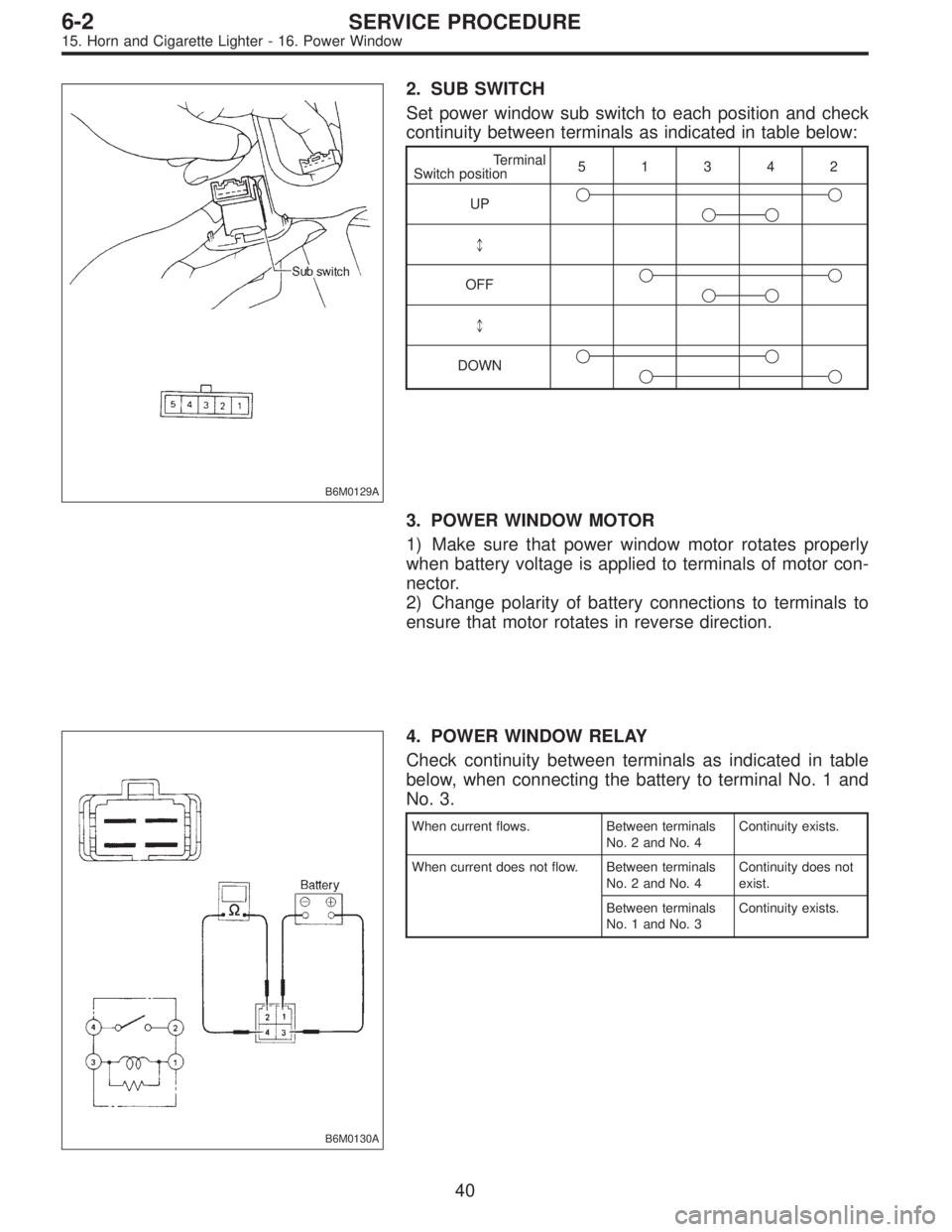
2. SUB SWITCH
Set power window sub switch to each position and check
continuity between terminals as indicated in table below:
Terminal
Switch position51342
UP��
��
*
OFF��
��
*
DOWN��
��
3. POWER WINDOW MOTOR
1) Make sure that power window motor rotates properly
when battery voltage is applied to terminals of motor con-
nector.
2) Change polarity of battery connections to terminals to
ensure that motor rotates in reverse direction.
B6M0130A
4. POWER WINDOW RELAY
Check continuity between terminals as indicated in table
below, when connecting the battery to terminal No. 1 and
No. 3.
When current flows. Between terminals
No. 2 and No. 4Continuity exists.
When current does not flow. Between terminals
No. 2 and No. 4Continuity does not
exist.
Between terminals
No. 1 and No. 3Continuity exists.
40
6-2SERVICE PROCEDURE
15. Horn and Cigarette Lighter - 16. Power Window
Page 1789 of 3342
![SUBARU LEGACY 1997 Service Repair Manual 19. Sunroof
A: REMOVAL AND INSTALLATION
1. SUNROOF AND SUNROOF MOTOR
Refer to 5-1 [W16A0] as for removal and installation of
sunroof system.
B6M0353A
2. SUNROOF SWITCH
NOTE:
The sunroof switch is inst](/manual-img/17/57434/w960_57434-1788.png "SUBARU LEGACY 1997 Service Repair Manual 19. Sunroof
A: REMOVAL AND INSTALLATION
1. SUNROOF AND SUNROOF MOTOR
Refer to 5-1 [W16A0] as for removal and installation of
sunroof system.
B6M0353A
2. SUNROOF SWITCH
NOTE:
The sunroof switch is inst")
19. Sunroof
A: REMOVAL AND INSTALLATION
1. SUNROOF AND SUNROOF MOTOR
Refer to 5-1 [W16A0] as for removal and installation of
sunroof system.
B6M0353A
2. SUNROOF SWITCH
NOTE:
The sunroof switch is installed in spot light body.
1) Pry spot light lens off using a screwdriver.
2) Remove screws which secure spot light body.
3) Remove spot light body while disconnecting connec-
tors.
4) Remove screw which secures sunroof switch, and then
remove sunroof switch.
B6M0142A
B: INSPECTION
1. SUNROOF SWITCH
Set sunroof switch to each position and check continuity
between terminals as indicated in table below:
Terminal
Switch position43652
Open��
Close��
Tilt up��
Tilt down��
B6M0503
2. SUNROOF MOTOR
1) Apply battery voltage between 1-pin connector and
body ground wire.
2) Make sure that sunroof motor moves when connecting
terminals as described below:
�Connect between terminals No. 3 and 4 (OPEN)
�Connect between terminals No. 6 and 4 (CLOSE)
�Connect between terminals No. 5 and 4 (TILT UP)
�Connect between terminals No. 2 and 4 (TILT DOWN)
45
6-2SERVICE PROCEDURE
19. Sunroof
Page 1790 of 3342
B6M0144A
3. SUNROOF RELAY
Check continuity between terminals as indicated in table
below, when battery voltage is applied between terminals
No. 1 and No. 3.
When current flows. Between terminals
No. 2 and No. 4Continuity exists.
When current does not flow. Between terminals
No. 2 and No. 4Continuity does not
exist.
Between terminals
No. 1 and No. 3Continuity exists.
B6M0354
20. Radio, Speaker and Antenna
A: REMOVAL AND INSTALLATION
1. RADIO BODY
1) Remove hand brake cover.
2) Remove console cover.
3) Remove screws which secure center panel. Remove
center panel.
B6M0355
4) Remove fitting screws, and slightly pull radio out of
instrument panel.
5) Disconnect connectors and antenna feeder cord.
B6M0146
2. FRONT SPEAKER
1) Remove gusset speaker from behind the rearview mir-
ror while disconnecting connector.
2) Remove door trim panel.
46
6-2SERVICE PROCEDURE
19. Sunroof - 20. Radio, Speaker and Antenna
Page 1791 of 3342
B6M0144A
3. SUNROOF RELAY
Check continuity between terminals as indicated in table
below, when battery voltage is applied between terminals
No. 1 and No. 3.
When current flows. Between terminals
No. 2 and No. 4Continuity exists.
When current does not flow. Between terminals
No. 2 and No. 4Continuity does not
exist.
Between terminals
No. 1 and No. 3Continuity exists.
B6M0354
20. Radio, Speaker and Antenna
A: REMOVAL AND INSTALLATION
1. RADIO BODY
1) Remove hand brake cover.
2) Remove console cover.
3) Remove screws which secure center panel. Remove
center panel.
B6M0355
4) Remove fitting screws, and slightly pull radio out of
instrument panel.
5) Disconnect connectors and antenna feeder cord.
B6M0146
2. FRONT SPEAKER
1) Remove gusset speaker from behind the rearview mir-
ror while disconnecting connector.
2) Remove door trim panel.
46
6-2SERVICE PROCEDURE
19. Sunroof - 20. Radio, Speaker and Antenna
Page 1797 of 3342
 Turn ignition switch ON.
2) Check that indicator light comes on when")
C: DRIVING TESTS
Conduct road tests by selecting a smooth, flat road or use
free rollers as road test simulation.
1. MAIN SWITCH
1) Turn ignition switch ON.
2) Check that indicator light comes on when main switch
is pressed (ON).
3) Check that indicator light goes out when main switch is
pressed again (OFF).
4) Turn ignition switch OFF with main switch ON (which is
indicated by illumination.).
5) Turn ignition switch ON again to ensure that indicator
light remains OFF.
2. COMMAND SWITCH
1) Check that command switch is properly set in“SET/
COAST”,“RESUME/ACCEL”or“CANCEL”mode.
2) Also check that command switch returns to the original
position when released.
3. CONSTANT SPEED TEST
1) Turn main switch ON.
2) Drive vehicle at speed greater than 40 km/h (25 MPH).
3) Press command switch to set in“SET/COAST”mode.
4) Ensure that vehicle is maintained at the speed set when
command switch was pressed.
4. ACCELERATION TEST
1) Set vehicle speed at speed greater than 40 km/h (25
MPH).
2) Ensure that vehicle continues to accelerate while hold-
ing command switch in RESUME/ACCEL mode, and that
vehicle maintains that optional speed when command
switch is released.
5. DECELERATION TEST
1) Set vehicle speed at optional speed greater than 40
km/h (25 MPH).
2) Ensure that vehicle continues to decelerate while hold-
ing command switch in SET/COAST mode, and that it
maintains that optional speed when command switch is
released.
NOTE:
When vehicle speed reaches the lower speed limit of 30
km/h (19 MPH) during deceleration, cruise control will be
released.
52
6-2SERVICE PROCEDURE
21. Cruise Control