Page 1661 of 3342

must not be disassembled. The airbag module cannot
be used again once inflated.
G5M0300
�When removing and install")
G5M0299
3. Airbag Module
CAUTION:
�The airbag module (driver side and passenger side)
must not be disassembled. The airbag module cannot
be used again once inflated.
G5M0300
�When removing and installing the airbag module
(driver side and passenger side), the operator should
stand, as much as possible, on the side of the airbag
module.
G5M0301
�After removal, the airbag module (driver side and
passenger side) should be kept away from heat and
light sources, and stored on a clean, flat surface to
prevent from any damage to its lower structure.
G5M0302
�Do not check airbag module (driver side and pas-
senger side) continuity with airbag removed from the
vehicle body.
�Replace airbag module (driver side and passenger
side) with a new one, should any of the following con-
ditions develop.
(1) Pad surface is scratched or cracked.
(2) Connector harness is damaged.
(3) Inflator side structure of module is cracked or
deformed.
(4) Module is excessively stained with water, oil, etc.
(5) Module was accidentally dropped.
10
5-5SERVICE PROCEDURE
3. Airbag Module
Page 1671 of 3342
G5M0323
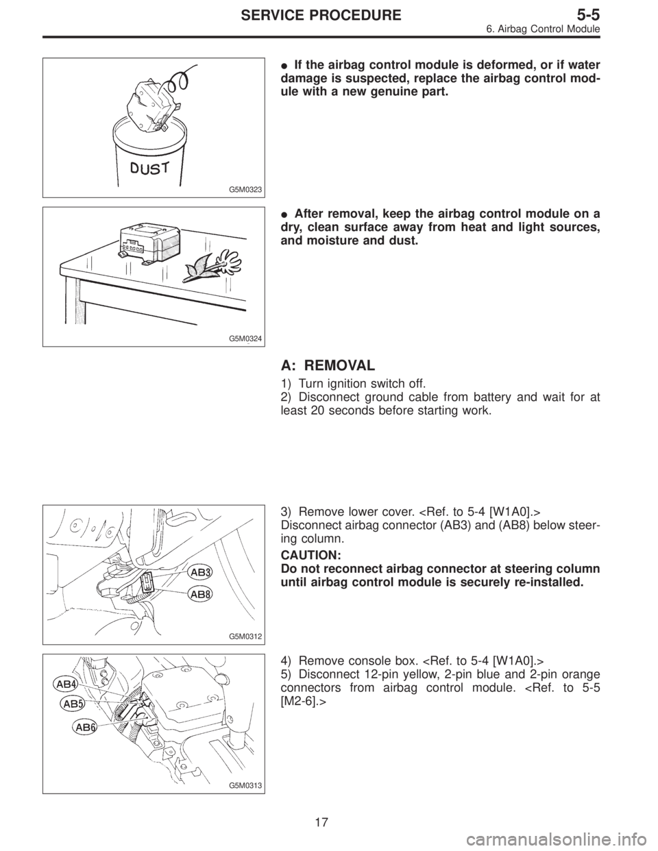
�If the airbag control module is deformed, or if water
damage is suspected, replace the airbag control mod-
ule with a new genuine part.
G5M0324
�After removal, keep the airbag control module on a
dry, clean surface away from heat and light sources,
and moisture and dust.
A: REMOVAL
1) Turn ignition switch off.
2) Disconnect ground cable from battery and wait for at
least 20 seconds before starting work.
G5M0312
3) Remove lower cover.
Disconnect airbag connector (AB3) and (AB8) below steer-
ing column.
CAUTION:
Do not reconnect airbag connector at steering column
until airbag control module is securely re-installed.
G5M0313
4) Remove console box.
5) Disconnect 12-pin yellow, 2-pin blue and 2-pin orange
connectors from airbag control module.
[M2-6].>
17
5-5SERVICE PROCEDURE
6. Airbag Control Module
Page 1680 of 3342
 Do not allow water or oil to come in contact with the
connector terminals. Do not touch the connector terminals.
9) When connecting or disconnecting airbag connector,
make sure ignition swi")
G5M0298
8) Do not allow water or oil to come in contact with the
connector terminals. Do not touch the connector terminals.
9) When connecting or disconnecting airbag connector,
make sure ignition switch is OFF.
2. Inspection and Replacement
Standards
1. VEHICLES WHICH BECOME INVOLVED IN A
COLLISION
If the vehicle equipped with an SRS airbag system is
damaged in a collision, the airbag system parts must
be checked and replaced in accordance with the fol-
lowing standards:
After faulty parts are replaced, the warning light opera-
tion must be checked.
�When the ignition switch is turned ON, it lights up
for about 7 seconds and then it goes out for at least 30
seconds.
�The trouble code stored in memory must be erased
after the check.
2. AIRBAG MODULE (DRIVER AND PASSENGER)
Inspection standard:
�The vehicle damaged in a collision (regardless of
whether or not airbag is deployed).
�The designated trouble code is output during self-diag-
nosis. (Refer to“Diagnostics”Section.)
Replacement standard:
�Airbag is deployed.
�The pad surface is scratched or cracked.
�Harness and/or connector is deformed or cracked, their
circuits are broken, lead wire is exposed, etc.
�Mounting bracket is cracked or deformed.
�The module surface is fouled with foreign matter.
(grease, oil, water, cleaning solvent, etc.)
�Airbag module dropped to the floor/ground.
�Airbag module determined as faulty during self-diagno-
sis.
6
5-5bSERVICE PROCEDURE
1. Precaution - 2. Inspection and Replacement Standards
Page 1681 of 3342
 Do not allow water or oil to come in contact with the
connector terminals. Do not touch the connector terminals.
9) When connecting or disconnecting airbag connector,
make sure ignition swi")
G5M0298
8) Do not allow water or oil to come in contact with the
connector terminals. Do not touch the connector terminals.
9) When connecting or disconnecting airbag connector,
make sure ignition switch is OFF.
2. Inspection and Replacement
Standards
1. VEHICLES WHICH BECOME INVOLVED IN A
COLLISION
If the vehicle equipped with an SRS airbag system is
damaged in a collision, the airbag system parts must
be checked and replaced in accordance with the fol-
lowing standards:
After faulty parts are replaced, the warning light opera-
tion must be checked.
�When the ignition switch is turned ON, it lights up
for about 7 seconds and then it goes out for at least 30
seconds.
�The trouble code stored in memory must be erased
after the check.
2. AIRBAG MODULE (DRIVER AND PASSENGER)
Inspection standard:
�The vehicle damaged in a collision (regardless of
whether or not airbag is deployed).
�The designated trouble code is output during self-diag-
nosis. (Refer to“Diagnostics”Section.)
Replacement standard:
�Airbag is deployed.
�The pad surface is scratched or cracked.
�Harness and/or connector is deformed or cracked, their
circuits are broken, lead wire is exposed, etc.
�Mounting bracket is cracked or deformed.
�The module surface is fouled with foreign matter.
(grease, oil, water, cleaning solvent, etc.)
�Airbag module dropped to the floor/ground.
�Airbag module determined as faulty during self-diagno-
sis.
6
5-5bSERVICE PROCEDURE
1. Precaution - 2. Inspection and Replacement Standards
Page 1685 of 3342

must not be disassembled. The airbag module cannot
be used again once inflated.
G5M0300
�When removing and install")
G5M0299
3. Airbag Module
CAUTION:
�The airbag module (driver side and passenger side)
must not be disassembled. The airbag module cannot
be used again once inflated.
G5M0300
�When removing and installing the airbag module
(driver side and passenger side), the operator should
stand, as much as possible, on the side of the airbag
module.
G5M0301
�After removal, the airbag module (driver side and
passenger side) should be kept away from heat and
light sources, and stored on a clean, flat surface to
prevent from any damage to its lower structure.
G5M0302
�Do not check airbag module (driver side and pas-
senger side) continuity with airbag removed from the
vehicle body.
�Replace airbag module (driver side and passenger
side) with a new one, should any of the following con-
ditions develop.
(1) Pad surface is scratched or cracked.
(2) Connector harness is damaged.
(3) Inflator side structure of module is cracked or
deformed.
(4) Module is excessively stained with water, oil, etc.
(5) Module was accidentally dropped.
10
5-5bSERVICE PROCEDURE
3. Airbag Module
Page 1692 of 3342
G5M0323
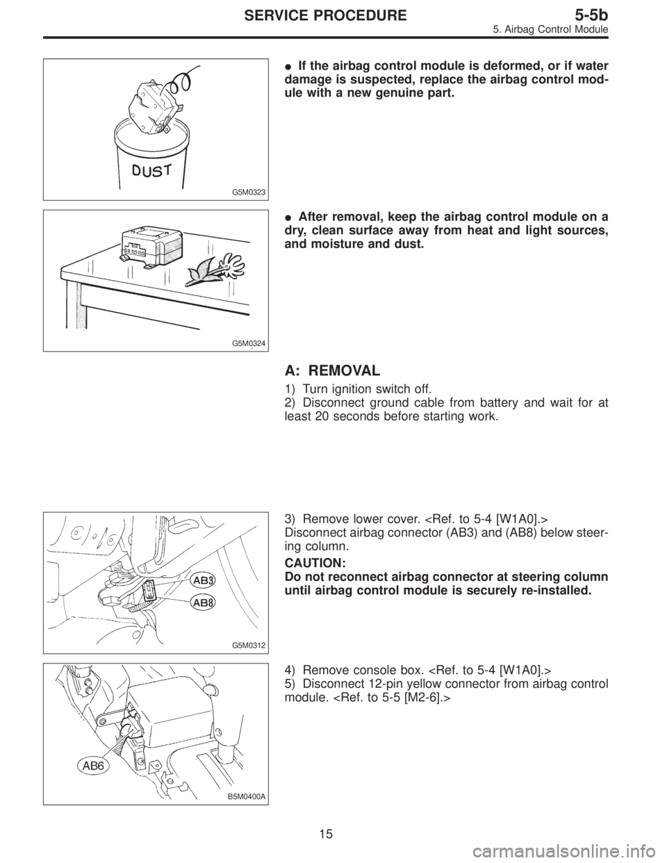
�If the airbag control module is deformed, or if water
damage is suspected, replace the airbag control mod-
ule with a new genuine part.
G5M0324
�After removal, keep the airbag control module on a
dry, clean surface away from heat and light sources,
and moisture and dust.
A: REMOVAL
1) Turn ignition switch off.
2) Disconnect ground cable from battery and wait for at
least 20 seconds before starting work.
G5M0312
3) Remove lower cover.
Disconnect airbag connector (AB3) and (AB8) below steer-
ing column.
CAUTION:
Do not reconnect airbag connector at steering column
until airbag control module is securely re-installed.
B5M0400A
4) Remove console box.
5) Disconnect 12-pin yellow connector from airbag control
module.
15
5-5bSERVICE PROCEDURE
5. Airbag Control Module
Page 1719 of 3342

NGK: BKR6E-11
NIPPONDENSO: K20PR-U1")
3. Spark Plug
A: REMOVAL AND INSTALLATION
CAUTION:
All spark plugs installed on an engine, must be of the
same heat range.
Spark plug:
CHAMPION: RC10YC4
(Alternate)
NGK: BKR6E-11
NIPPONDENSO: K20PR-U11
1) Remove spark plug cords by pulling boot, not cord itself.
2) Remove spark plugs.
3) When installing spark plugs on cylinder head, use spark
plug wrench.
Tightening torque (Spark plug):
20.6±2.9 N⋅m (2.10±0.30 kg-m, 15.19±2.14 ft-lb)
CAUTION:
The above torque should be only applied to new spark
plugs without oil on their threads.
In case their threads are lubricated, the torque should
be reduced by approximately 1/3 of the specified
torque in order to avoid their over-stressing.
4) Connect spark plug cords.
G6M0086
B: INSPECTION
Check electrodes and inner and outer porcelain of plugs,
noting the type of deposits and the degree of electrode
erosion.
G6M0087
1) Normal
Brown to grayish-tan deposits and slight electrode wear
indicate correct spark plug heat range.
23
6-1SERVICE PROCEDURE
3. Spark Plug
Page 1720 of 3342
 Carbon fouled
Dry fluffy carbon deposits on insulator and electrode are
mostly caused by slow speed driving in city, weak ignition,
too rich fuel mixture, dirty air cleaner, etc.
It is advi")
G6M0088
2) Carbon fouled
Dry fluffy carbon deposits on insulator and electrode are
mostly caused by slow speed driving in city, weak ignition,
too rich fuel mixture, dirty air cleaner, etc.
It is advisable to replace with plugs having hotter heat
range.
G6M0089
3) Oil fouled
Wet black deposits show excessive oil entrance into com-
bustion chamber through worn rings and pistons or exces-
sive clearance between valve guides and stems. If same
condition remains after repair, use a hotter plug.
G6M0090
4) Overheating
White or light gray insulator with black or gray brown spots
and bluish burnt electrodes indicate engine overheating.
Moreover, the appearance results from incorrect ignition
timing, loose spark plugs, wrong selection of fuel, hotter
range plug, etc. It is advisable to replace with plugs having
colder heat range.
G6M0091
C: CLEANING AND REGAPPING
Clean spark plugs in a sand blast type cleaner.
Avoid excessive blasting. Clean and remove carbon or
oxide deposits, but do not wear away porcelain.
If deposits are too stubborn, discard plugs.
After cleaning spark plugs, recondition firing surface of
electrodes with file. Then correct the spark plug gap using
a gap gauge.
Spark plug gap: L
1.0—1.1 mm (0.039—0.043 in)
D: REMOVAL AND INSTALLATION (2500 cc
EXCEPT OUTBACK MODEL)
CAUTION:
All spark plugs installed on an engine, must be of the
same heat range.
Spark plug:
NGK: PFR5B-11
24
6-1SERVICE PROCEDURE
3. Spark Plug