Page 2164 of 3342
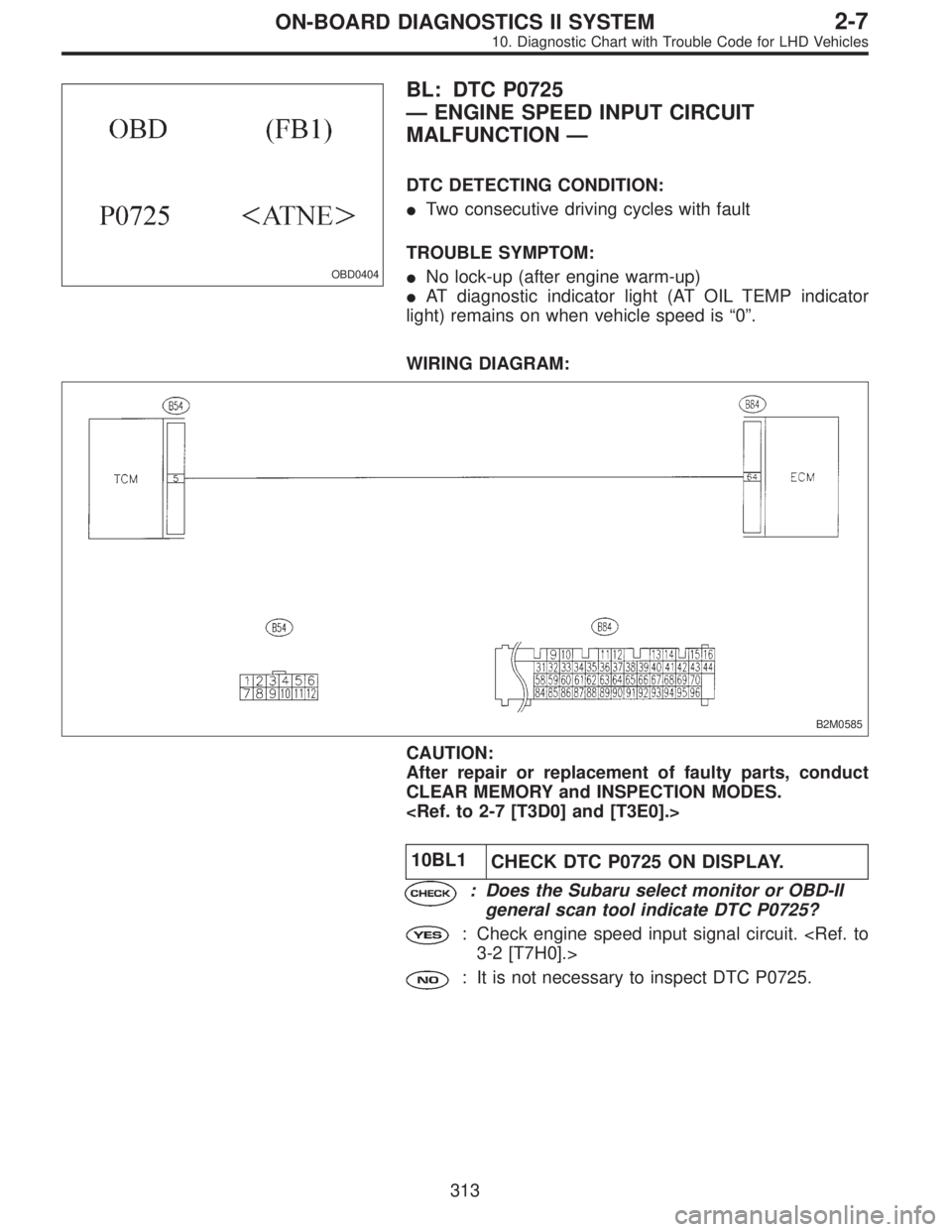
OBD0404
BL: DTC P0725
—ENGINE SPEED INPUT CIRCUIT
MALFUNCTION—
DTC DETECTING CONDITION:
�Two consecutive driving cycles with fault
TROUBLE SYMPTOM:
�No lock-up (after engine warm-up)
�AT diagnostic indicator light (AT OIL TEMP indicator
light) remains on when vehicle speed is“0”.
WIRING DIAGRAM:
B2M0585
CAUTION:
After repair or replacement of faulty parts, conduct
CLEAR MEMORY and INSPECTION MODES.
10BL1
CHECK DTC P0725 ON DISPLAY.
: Does the Subaru select monitor or OBD-II
general scan tool indicate DTC P0725?
: Check engine speed input signal circuit.
3-2 [T7H0].>
: It is not necessary to inspect DTC P0725.
313
2-7ON-BOARD DIAGNOSTICS II SYSTEM
10. Diagnostic Chart with Trouble Code for LHD Vehicles
Page 2170 of 3342
10BQ5CHECK VEHICLE SPEED SENSOR 2 CIR-
CUIT.
Check vehicle speed sensor 2 circuit.
: Is there any trouble in vehicle speed sensor
2 circuit?
: Repair or replace vehicle speed sensor 2 circuit.
: Go to step10BQ6.
10BQ6
CHECK ENGINE SPEED INPUT CIRCUIT.
Check engine speed input circuit.
: Is there any trouble in engine speed input
circuit?
: Repair or replace engine speed input circuit.
: Go to step10BQ7.
10BQ7
CHECK INHIBITOR SWITCH CIRCUIT.
Check inhibitor switch circuit.
: Is there any trouble in inhibitor switch cir-
cuit?
: Repair or replace inhibitor switch circuit.
: Go to step10BQ8.
10BQ8
CHECK BRAKE LIGHT SWITCH CIRCUIT.
Check brake light switch circuit.
: Is there any trouble in brake light switch cir-
cuit?
: Repair or replace brake light switch circuit.
: Go to step10BQ9.
319
2-7ON-BOARD DIAGNOSTICS II SYSTEM
10. Diagnostic Chart with Trouble Code for LHD Vehicles
Page 2197 of 3342
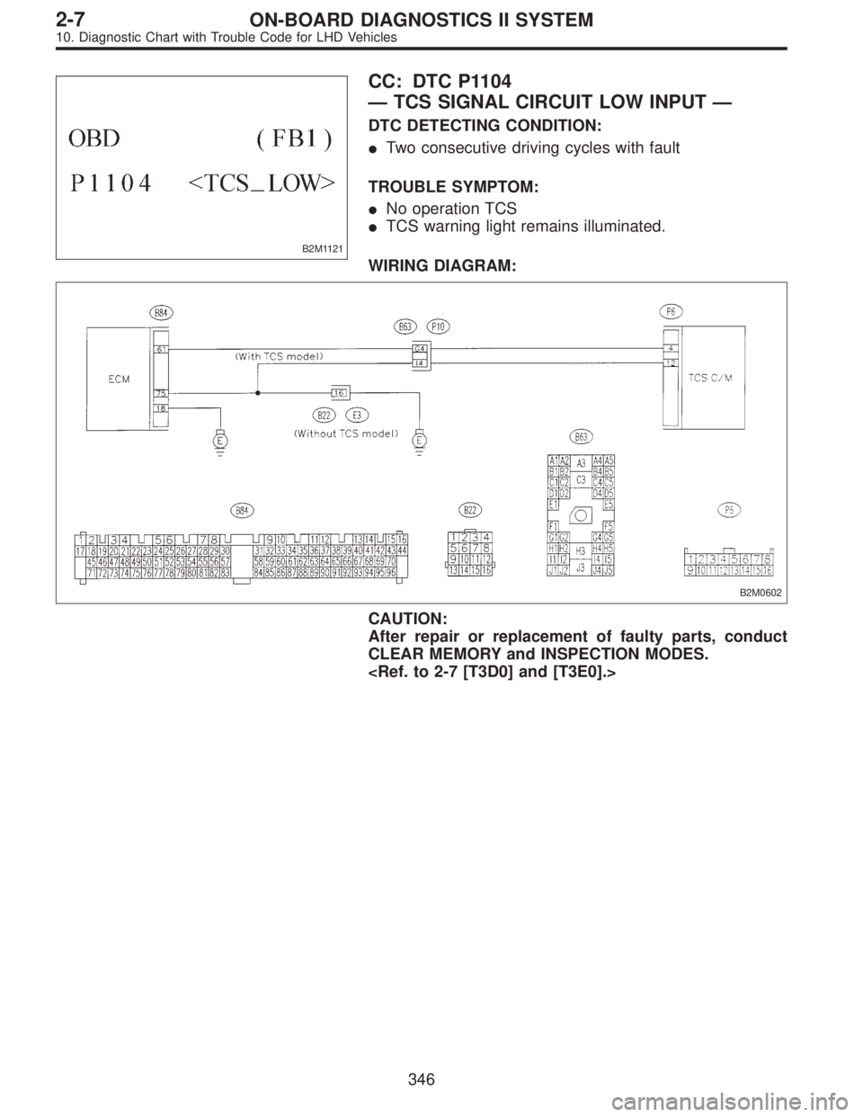
B2M1121
CC: DTC P1104
—TCS SIGNAL CIRCUIT LOW INPUT—
DTC DETECTING CONDITION:
�Two consecutive driving cycles with fault
TROUBLE SYMPTOM:
�No operation TCS
�TCS warning light remains illuminated.
WIRING DIAGRAM:
B2M0602
CAUTION:
After repair or replacement of faulty parts, conduct
CLEAR MEMORY and INSPECTION MODES.
346
2-7ON-BOARD DIAGNOSTICS II SYSTEM
10. Diagnostic Chart with Trouble Code for LHD Vehicles
Page 2202 of 3342
10CE1
CHECK DTC P0705 ON DISPLAY.
: Does the Subaru select monitor or OBD-II
general scan tool indicate DTC P0705?
: Inspect DTC P0705 using“10. Diagnostics Chart
with Trouble Code”.
: Go to step10CE2.
B2M0593A
10CE2
CHECK INPUT SIGNAL FOR ECM.
1) Turn ignition switch to ON.
2) Measure voltage between ECM and chassis ground.
: Connector & terminal
(B84) No. 82 (+)—Chassis ground (�):
Is the voltage between 4.5 and 5.5 V in other
positions?
: Even if MIL lights up, the circuit has returned to a
normal condition at this time.
: Go to step10CE3.
10CE3
CHECK INHIBITOR SWITCH TYPE.
: Is inhibitor switch type plastic body?
: Go to step10CE4.
: Go to step10CE7.
351
2-7ON-BOARD DIAGNOSTICS II SYSTEM
10. Diagnostic Chart with Trouble Code for LHD Vehicles
Page 2208 of 3342
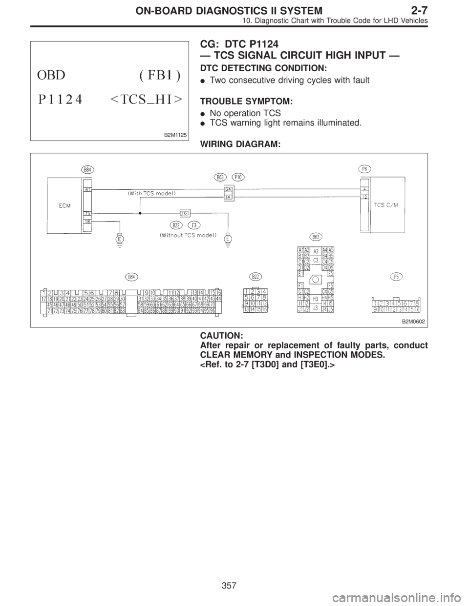
B2M1125
CG: DTC P1124
—TCS SIGNAL CIRCUIT HIGH INPUT—
DTC DETECTING CONDITION:
�Two consecutive driving cycles with fault
TROUBLE SYMPTOM:
�No operation TCS
�TCS warning light remains illuminated.
WIRING DIAGRAM:
B2M0602
CAUTION:
After repair or replacement of faulty parts, conduct
CLEAR MEMORY and INSPECTION MODES.
357
2-7ON-BOARD DIAGNOSTICS II SYSTEM
10. Diagnostic Chart with Trouble Code for LHD Vehicles
Page 2217 of 3342
 Measure actual atmospheric pressure.
2) Read data on Subaru Select Monitor or OBD-II general
scan tool.
�Subaru Select Monitor
Designate mode using function key")
B2M0755
10CJ2
CHECK PRESSURE SENSOR.
1) Measure actual atmospheric pressure.
2) Read data on Subaru Select Monitor or OBD-II general
scan tool.
�Subaru Select Monitor
Designate mode using function key.
Function mode: F20
�F20: Display shows pressure signal value sent from the
pressure sensor.
: Is the difference between absolute value of
Subaru Selector Monitor indication and
actual atmospheric pressure greater than 10
kPa (0.102 kg/cm
2, 1.45 psi)?
: Replace pressure sensor.
: Even if MIL lights up, the circuit has returned to a
normal condition at this time. Contact with SOA
service.
NOTE:
Inspection by DTM is required, because probable cause is
deterioration of multiple parts.
B2M1162A
B2M1163A
10CJ3
CHECK VACUUM HOSE.
: Is there a fault in vacuum hose?
NOTE:
Check the following item.
Incorrect hose connections in line between the pressure
sources switching solenoid valve and pressure sensor,
intake manifold and/or CPC solenoid valve.
: Repair or replace hoses or filter.
: Go to step10CJ4.
366
2-7ON-BOARD DIAGNOSTICS II SYSTEM
10. Diagnostic Chart with Trouble Code for LHD Vehicles
Page 2220 of 3342
 Turn ignition switch to OFF.
2) Connect Subaru Select Monitor or the OBD-II general
scan tool to data link connector.
3) Turn ignition switch ON and Subaru Se")
OBD0145A
10CK1
CHECK DATA FOR CONTROL.
1) Turn ignition switch to OFF.
2) Connect Subaru Select Monitor or the OBD-II general
scan tool to data link connector.
3) Turn ignition switch ON and Subaru Select Monitor or
the OBD-II general scan tool switch ON.
4) Start engine.
5) Read data on Subaru Select Monitor or the OBD-II gen-
eral scan tool.
�Subaru Select Monitor
Designate mode using function key.
Function mode: F20
�F20: Display shows pressure signal value sent from the
pressure sensor.
B2M0755
: Is the value more than 133 kPa in function
mode F20?
: Replace pressure sensor.
: Even if MIL lights up, the circuit has returned to a
normal condition at this time. Contact with SOA
service.
NOTE:
Inspection by DTM is required, because probable cause is
deterioration of multiple parts.
�OBD-II general scan tool
For detailed operation procedures, refer to the OBD-II Gen-
eral Scan Tool Instruction Manual.
369
2-7ON-BOARD DIAGNOSTICS II SYSTEM
10. Diagnostic Chart with Trouble Code for LHD Vehicles
Page 2257 of 3342
 Turn ignition switch to OFF.
2) Connect test mode connector at the lower portion of
instrument panel (on the driver’s side), to the side of the
center")
OBD0736A
10CW1
CHECK OUTPUT SIGNAL FROM ECM.
1) Turn ignition switch to OFF.
2) Connect test mode connector at the lower portion of
instrument panel (on the driver’s side), to the side of the
center console box.
3) Turn ignition switch to ON.
B2M0608A
4) Measure voltage between ECM and chassis ground.
: Connector & terminal
(B84) No. 74 (+)—Chassis ground:
Does voltage change between 0 and 10
volts?
NOTE:
Radiator fan relay operation check can be executed using
Subaru Select Monitor (Function mode: FD03). For
procedure, refer to“COMPULSORY VALVE OPERATION
CHECK MODE”.
: Go to step10CW2.
: Even if MIL lights up, the circuit has returned to a
normal condition at this time. In this case, repair
poor contact in ECM connector.
B2M0611A
10CW2CHECK SHORT CIRCUIT IN RADIATOR
FAN RELAY 1 CONTROL CIRCUIT.
1) Turn ignition switch to OFF.
2) Remove main fan relay 1 and sub fan relay 1. (with A/C
models)
Remove main fan relay. (without A/C models)
3) Disconnect test mode connector.
4) Turn ignition switch to ON.
5) Measure voltage between ECM and chassis ground.
: Connector & terminal
(B84) No. 74 (+)—Chassis ground (�):
Is the voltage more than 10 V?
: Repair battery short circuit in radiator fan relay 1
control circuit. After repair, replace ECM.
: Go to next.
: Is there poor contact in ECM connector?
: Repair poor contact in ECM connector.
: Replace ECM.
406
2-7ON-BOARD DIAGNOSTICS II SYSTEM
10. Diagnostic Chart with Trouble Code for LHD Vehicles
![SUBARU LEGACY 1997 Service Repair Manual 10BQ5CHECK VEHICLE SPEED SENSOR 2 CIR-
CUIT.
Check vehicle speed sensor 2 circuit. <Ref. to 3-2 [T7M0].>
: Is there any trouble in vehicle speed sensor
2 circuit?
: Repair or replace vehicle speed sen](/manual-img/17/57434/w960_57434-2169.png "SUBARU LEGACY 1997 Service Repair Manual 10BQ5CHECK VEHICLE SPEED SENSOR 2 CIR-
CUIT.
Check vehicle speed sensor 2 circuit. <Ref. to 3-2 [T7M0].>
: Is there any trouble in vehicle speed sensor
2 circuit?
: Repair or replace vehicle speed sen")