Page 1064 of 3342
G3M0078
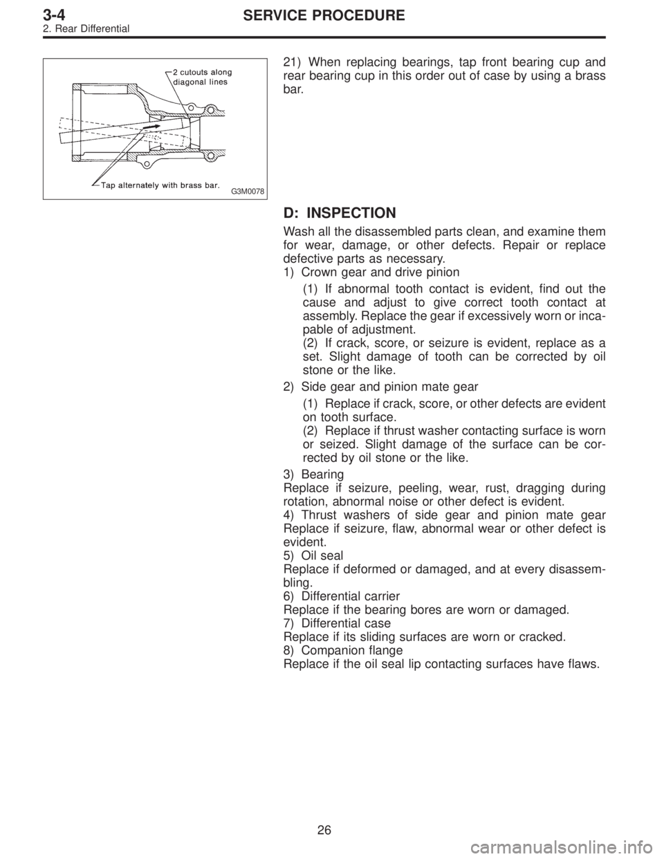
21) When replacing bearings, tap front bearing cup and
rear bearing cup in this order out of case by using a brass
bar.
D: INSPECTION
Wash all the disassembled parts clean, and examine them
for wear, damage, or other defects. Repair or replace
defective parts as necessary.
1) Crown gear and drive pinion
(1) If abnormal tooth contact is evident, find out the
cause and adjust to give correct tooth contact at
assembly. Replace the gear if excessively worn or inca-
pable of adjustment.
(2) If crack, score, or seizure is evident, replace as a
set. Slight damage of tooth can be corrected by oil
stone or the like.
2) Side gear and pinion mate gear
(1) Replace if crack, score, or other defects are evident
on tooth surface.
(2) Replace if thrust washer contacting surface is worn
or seized. Slight damage of the surface can be cor-
rected by oil stone or the like.
3) Bearing
Replace if seizure, peeling, wear, rust, dragging during
rotation, abnormal noise or other defect is evident.
4) Thrust washers of side gear and pinion mate gear
Replace if seizure, flaw, abnormal wear or other defect is
evident.
5) Oil seal
Replace if deformed or damaged, and at every disassem-
bling.
6) Differential carrier
Replace if the bearing bores are worn or damaged.
7) Differential case
Replace if its sliding surfaces are worn or cracked.
8) Companion flange
Replace if the oil seal lip contacting surfaces have flaws.
26
3-4SERVICE PROCEDURE
2. Rear Differential
Page 1074 of 3342
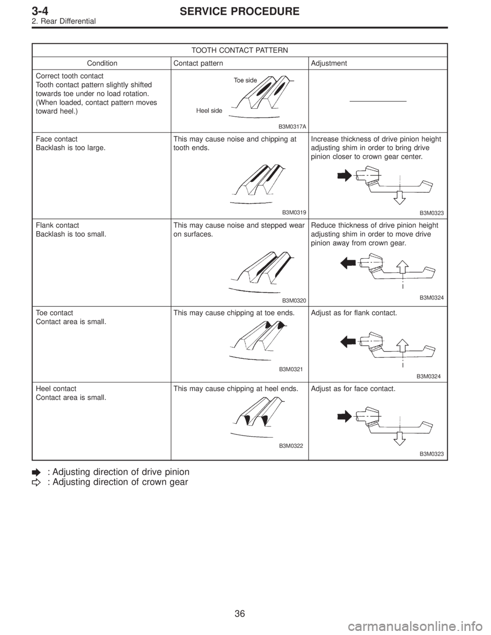
TOOTH CONTACT PATTERN
Condition Contact pattern Adjustment
Correct tooth contact
Tooth contact pattern slightly shifted
towards toe under no load rotation.
(When loaded, contact pattern moves
toward heel.)
B3M0317A
Face contact
Backlash is too large.This may cause noise and chipping at
tooth ends.
B3M0319
Increase thickness of drive pinion height
adjusting shim in order to bring drive
pinion closer to crown gear center.
B3M0323
Flank contact
Backlash is too small.This may cause noise and stepped wear
on surfaces.
B3M0320
Reduce thickness of drive pinion height
adjusting shim in order to move drive
pinion away from crown gear.
B3M0324
Toe contact
Contact area is small.This may cause chipping at toe ends.
B3M0321
Adjust as for flank contact.
B3M0324
Heel contact
Contact area is small.This may cause chipping at heel ends.
B3M0322
Adjust as for face contact.
B3M0323
: Adjusting direction of drive pinion
: Adjusting direction of crown gear
36
3-4SERVICE PROCEDURE
2. Rear Differential
Page 1127 of 3342
G4M0208
1. Wheels and Axles
A: SPECIFICATIONS
1. TIRE AND WHEEL SIZE
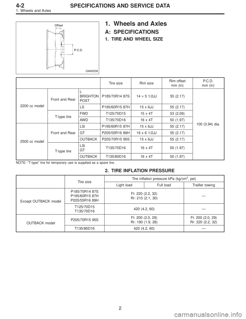
Tire size Rim sizeRim offset
mm (in)P.C.D.
mm (in)
2200 cc modelFront and RearL
BRIGHTON
POSTP185/70R14 87S 14×5 1/2JJ 55 (2.17)
100 (3.94) dia. LS P195/60R15 87H 15 x 6JJ 55 (2.17)
T-type tireFWD T125/70D15 15 x 4T 53 (2.09)
AWD T135/70D16 16 x 4T 50 (1.97)
2500 cc modelFront and RearLSi P195/60R15 87H 15 x 6JJ 55 (2.17)
GT P205/55R16 89H 16 x 6 1/2JJ 55 (2.17)
OUTBACK P205/70R15 95S 15 x 6JJ 55 (2.17)
T-type tireLSi
GTT135/70D16 16 x 4T 50 (1.97)
OUTBACK T135/80D16 16 x 4T 50 (1.97)
NOTE:“T-type”tire for temporary use is supplied as a spare tire.
2. TIRE INFLATION PRESSURE
Tire sizeTire inflation pressure kPa (kg/cm
2, psi)
Light load Full load Trailler towing
Except OUTBACK modelP185/70R14 87S
P195/60R15 87H
P205/55R16 89HFt: 220 (2.2, 32)
Rr: 210 (2.1, 30)—
T125/70D15
T135/70D16420 (4.2, 60)—
OUTBACK modelP205/70R15 95SFt: 200 (2.0, 29)
Rr: 190 (1.9, 28)Ft: 200 (2.0, 29)
Rr: 220 (2.2, 32)
T135/80D16 420 (4.2, 60)—
2
4-2SPECIFICATIONS AND SERVICE DATA
1. Wheels and Axles
Page 1129 of 3342
4. REAR DRIVE SHAFT ASSEMBLY (AWD MODEL)
Type of drive shaft assemblySHAFT
No. of identification paddings on shaft
79AC-RH 1 (One)
79AC-LH 1 (One)
B4M0547A
5. APPLICATION TABLE
Model Power unitFront drive shaft
Rear drive shaft
5MT 4AT
FWD 2200 cc UFJ95+DOJ95 BJ87L+DOJ82RPC-F—
AWD 2200 cc BJ87L+DOJ82RPC-F BJ87L+DOJ82RPC-F 79AC-RH, 79AC-LH
AWD 2500 cc BJ87L+DOJ82RPC-F BJ87L+FTJ87 79AC-RH, 79AC-LH
B: SERVICE DATA
Use specified grease.
Front:
UFJ, BJ — NTG2218 (Part No. 28093AA020)
DOJ (except 2200 cc FWD MT model)
— VU-3A702 (Yellow) (Part No. 23223GA050)
DOJ (2200 cc FWD MT model)
— Molylex No. 2 (Part No. 723223010)
or Sunlight TB2-A
FTJ — SSG 6003 (Part No. 28093TA010)
Rear:
BJ — Molylex No. 2 (Part No. 723223010)
or Sunlight TB2-A
DOJ — VU-3A702 (Yellow) (Part No. 23223GA050)
4
4-2SPECIFICATIONS AND SERVICE DATA
1. Wheels and Axles
Page 1155 of 3342
Tightening torque:
186±20 N⋅m (19±2 kg-m, 137±14 ft-lb)
CAUTION:
�Use a new axle nut.
�Always tighten axle nut before installing wheel on
vehicle. If wheel is installed and comes in contact with
ground when axle nut is loose, wheel bearings may be
damaged.
�Be sure to tighten axle nut to specified torque. Do
not overtighten it as this may damage wheel bearing.
12) Install O-ring to hub cap flange, and install hub cap by
lightly tapping it with a plastic-faced hammer.
13) Install wheel and tighten wheel nuts to specified
torque.
Tightening torque (Wheel nut):
88±10 N⋅m (9±1 kg-m, 65±7 ft-lb)
4. Front and Rear Drive Shafts
A: REMOVAL
1. FRONT DRIVE SHAFT
1) Disconnect ground cable from battery.
2) Jack-up vehicle, support it with safety stands (rigid
racks), and remove front wheel cap and wheels.
3) Unlock axle nut.
4) While depressing brake pedal, remove axle nut using a
socket wrench.
CAUTION:
Be sure to loosen and retighten axle nut after remov-
ing wheel from vehicle. Failure to follow this rule may
damage wheel bearings.
5) Disconnect stabilizer link from transverse link.
6) Disconnect transverse link from housing.
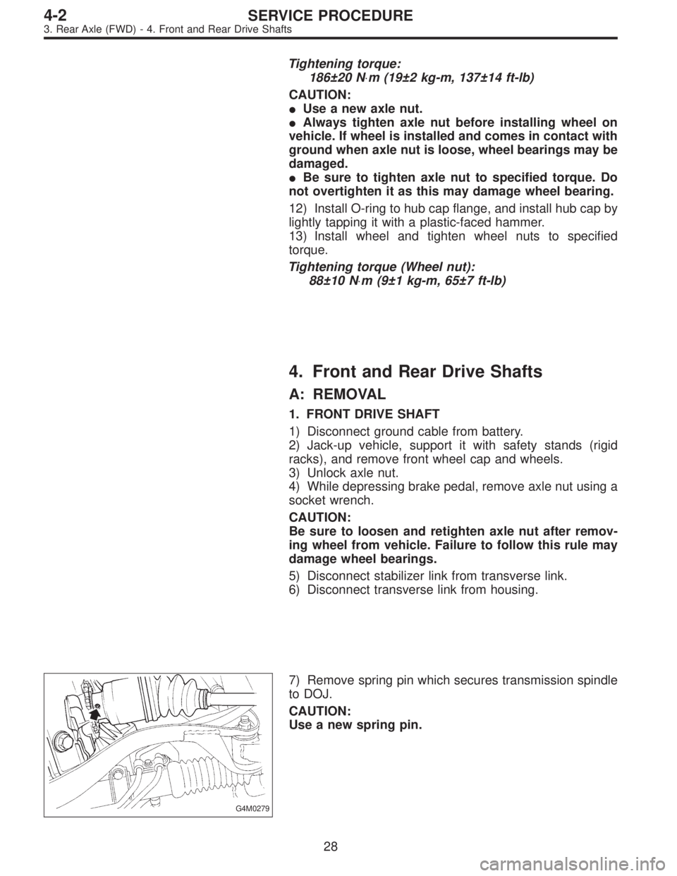
G4M0279
7) Remove spring pin which secures transmission spindle
to DOJ.
CAUTION:
Use a new spring pin.
28
4-2SERVICE PROCEDURE
3. Rear Axle (FWD) - 4. Front and Rear Drive Shafts
Page 1162 of 3342
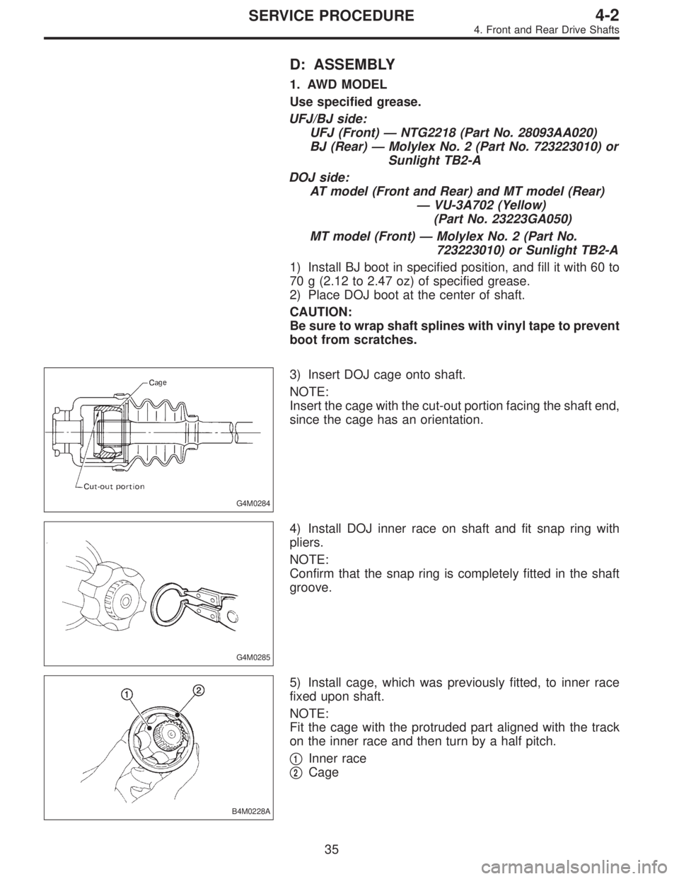
D: ASSEMBLY
1. AWD MODEL
Use specified grease.
UFJ/BJ side:
UFJ (Front)—NTG2218 (Part No. 28093AA020)
BJ (Rear)—Molylex No. 2 (Part No. 723223010) or
Sunlight TB2-A
DOJ side:
AT model (Front and Rear) and MT model (Rear)
—VU-3A702 (Yellow)
(Part No. 23223GA050)
MT model (Front)—Molylex No. 2 (Part No.
723223010) or Sunlight TB2-A
1) Install BJ boot in specified position, and fill it with 60 to
70 g (2.12 to 2.47 oz) of specified grease.
2) Place DOJ boot at the center of shaft.
CAUTION:
Be sure to wrap shaft splines with vinyl tape to prevent
boot from scratches.
G4M0284
3) Insert DOJ cage onto shaft.
NOTE:
Insert the cage with the cut-out portion facing the shaft end,
since the cage has an orientation.
G4M0285
4) Install DOJ inner race on shaft and fit snap ring with
pliers.
NOTE:
Confirm that the snap ring is completely fitted in the shaft
groove.
B4M0228A
5) Install cage, which was previously fitted, to inner race
fixed upon shaft.
NOTE:
Fit the cage with the protruded part aligned with the track
on the inner race and then turn by a half pitch.
�
1Inner race
�
2Cage
35
4-2SERVICE PROCEDURE
4. Front and Rear Drive Shafts
Page 1163 of 3342
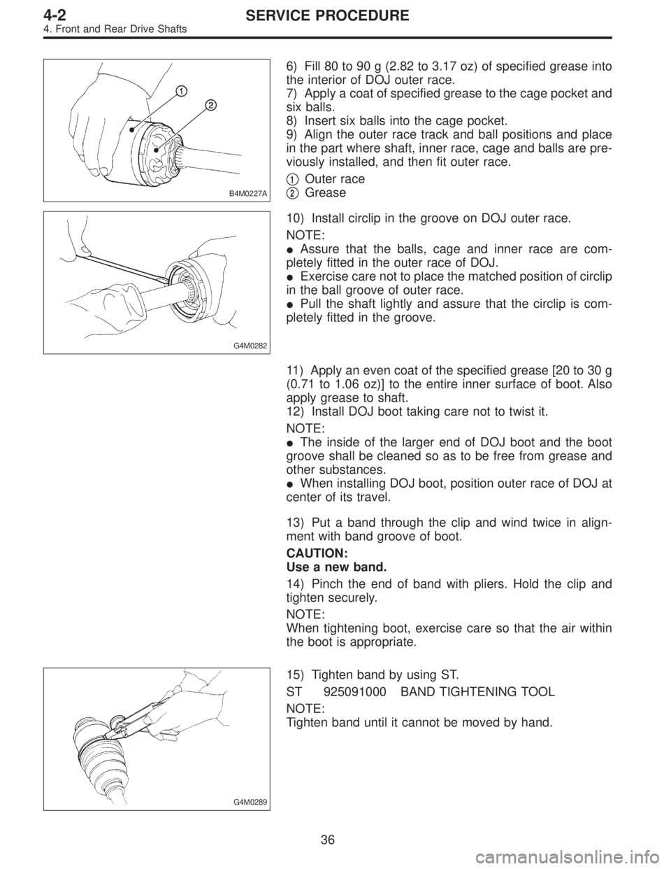
B4M0227A
6) Fill 80 to 90 g (2.82 to 3.17 oz) of specified grease into
the interior of DOJ outer race.
7) Apply a coat of specified grease to the cage pocket and
six balls.
8) Insert six balls into the cage pocket.
9) Align the outer race track and ball positions and place
in the part where shaft, inner race, cage and balls are pre-
viously installed, and then fit outer race.
�
1Outer race
�
2Grease
G4M0282
10) Install circlip in the groove on DOJ outer race.
NOTE:
�Assure that the balls, cage and inner race are com-
pletely fitted in the outer race of DOJ.
�Exercise care not to place the matched position of circlip
in the ball groove of outer race.
�Pull the shaft lightly and assure that the circlip is com-
pletely fitted in the groove.
11) Apply an even coat of the specified grease [20 to 30 g
(0.71 to 1.06 oz)] to the entire inner surface of boot. Also
apply grease to shaft.
12) Install DOJ boot taking care not to twist it.
NOTE:
�The inside of the larger end of DOJ boot and the boot
groove shall be cleaned so as to be free from grease and
other substances.
�When installing DOJ boot, position outer race of DOJ at
center of its travel.
13) Put a band through the clip and wind twice in align-
ment with band groove of boot.
CAUTION:
Use a new band.
14) Pinch the end of band with pliers. Hold the clip and
tighten securely.
NOTE:
When tightening boot, exercise care so that the air within
the boot is appropriate.
G4M0289
15) Tighten band by using ST.
ST 925091000 BAND TIGHTENING TOOL
NOTE:
Tighten band until it cannot be moved by hand.
36
4-2SERVICE PROCEDURE
4. Front and Rear Drive Shafts
Page 1164 of 3342
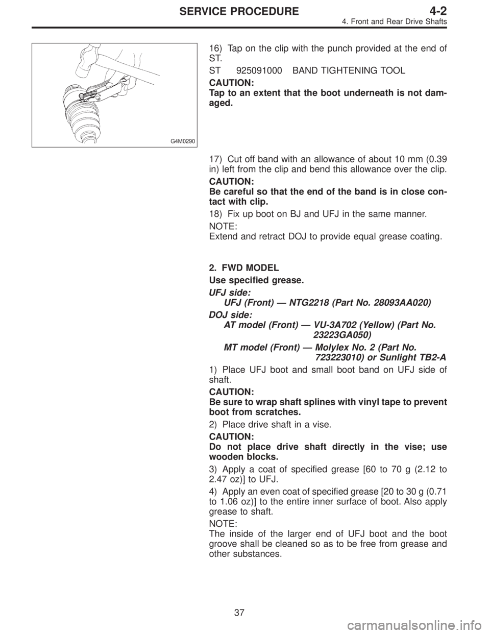
G4M0290
16) Tap on the clip with the punch provided at the end of
ST.
ST 925091000 BAND TIGHTENING TOOL
CAUTION:
Tap to an extent that the boot underneath is not dam-
aged.
17) Cut off band with an allowance of about 10 mm (0.39
in) left from the clip and bend this allowance over the clip.
CAUTION:
Be careful so that the end of the band is in close con-
tact with clip.
18) Fix up boot on BJ and UFJ in the same manner.
NOTE:
Extend and retract DOJ to provide equal grease coating.
2. FWD MODEL
Use specified grease.
UFJ side:
UFJ (Front)—NTG2218 (Part No. 28093AA020)
DOJ side:
AT model (Front)—VU-3A702 (Yellow) (Part No.
23223GA050)
MT model (Front)—Molylex No. 2 (Part No.
723223010) or Sunlight TB2-A
1) Place UFJ boot and small boot band on UFJ side of
shaft.
CAUTION:
Be sure to wrap shaft splines with vinyl tape to prevent
boot from scratches.
2) Place drive shaft in a vise.
CAUTION:
Do not place drive shaft directly in the vise; use
wooden blocks.
3) Apply a coat of specified grease [60 to 70 g (2.12 to
2.47 oz)] to UFJ.
4) Apply an even coat of specified grease [20 to 30 g (0.71
to 1.06 oz)] to the entire inner surface of boot. Also apply
grease to shaft.
NOTE:
The inside of the larger end of UFJ boot and the boot
groove shall be cleaned so as to be free from grease and
other substances.
37
4-2SERVICE PROCEDURE
4. Front and Rear Drive Shafts