Page 969 of 3342
 Apply red lead evenly to the surfaces of three or
four teeth of the crown gear. Rotate the drive pinion in
the forward and reverse directions several times. Then
remove the oil pump housing, and c")
(8) Apply red lead evenly to the surfaces of three or
four teeth of the crown gear. Rotate the drive pinion in
the forward and reverse directions several times. Then
remove the oil pump housing, and check the tooth con-
tact pattern.
If tooth contact is improper, readjust the backlash or
shim thickness.
Checking item Contact pattern Corrective action
Tooth contact
Tooth contact pattern is slightly shifted
toward to under no-load rotation.
[When loaded, contact pattern moves
toward heel.]
B3M0317A
Face contact
Backlash is too large.This may cause noise and chipping at
tooth ends.
B3M0319
Increase thickness of drive pinion height
adjusting shim in order to bring drive pinion
close to crown gear.
B3M0323
Flank contact
Backlash is too small.This may cause noise and stepped wear
on surfaces.
B3M0320
Reduce thickness of drive pinion height
adjusting shim in order to move drive pin-
ion away from crown gear.
B3M0324
Toe contact
(Inside end contact)
Contact areas is small.This may cause chipping at toe ends.
B3M0321
Adjust as for flank contact.
B3M0324
Heel contact
(Outside end contact)
Contact area is small.This may cause chipping at heel ends.
B3M0322
Adjust as for face contact.
B3M0323
: Adjusting direction of drive pinion
: Adjusting direction of crown gear
63
3-2SERVICE PROCEDURE
4. Overall Transmission
Page 988 of 3342
 Insert the input shaft while turning lightly by hand.
CAUTION:
Be careful not to damage the bushing.
Normal protrusion A:
2200 cc: 50—55 mm (1.97—2.17 in)
2500 cc: 28—32 mm (1.10—")
B3M0630A
11) Insert the input shaft while turning lightly by hand.
CAUTION:
Be careful not to damage the bushing.
Normal protrusion A:
2200 cc: 50—55 mm (1.97—2.17 in)
2500 cc: 28—32 mm (1.10—1.26 in)
B3M0632A
12) Install the torque converter clutch assembly.
(1) Install the oil pump shaft to the torque converter
clutch.
NOTE:
Make sure the clip fits securely in its groove.
(2) Holding the torque converter clutch assembly by
hand, carefully install it to the torque converter clutch
case. Be careful not to damage the bushing. Also avoid
undue contact between the oil pump shaft bushing and
stator shaft portion of the oil pump cover.
(3) Rotate the shaft lightly by hand to engage the
splines securely.
Dimension A:
2200 cc: 3.9—4.1 mm (0.154—0.161 in)
2500 cc: 7.9—8.1 mm (0.311—0.319 in)
13) Fill ATF and differential gear oil.
Differential gear oil capacity:
1.1—1.3�(1.2—1.4 US qt, 1.0—1.1 Imp qt)
Automatic transmission fluid capacity:
2200 cc:
7.9—8.2�(8.4—8.7 US qt, 7.0—7.2 Imp qt)
2500 cc:
9.5—9.8�(10.0—10.3 US qt, 8.4—8.6 lmp qt)
Recommended fluid:
Dexron II or Dexron III type automatic transmis-
sion
NOTE:
After filling oil, insert the oil level gauge into the oil inlet.
82
3-2SERVICE PROCEDURE
4. Overall Transmission
Page 997 of 3342
G3M0446
2) Remove the oil pump cover.
NOTE:
Lightly tap the end of the stator shaft to remove the cover.
G3M0447
3) Remove the retainer and return spring. Then remove
the rotor, two vane rings and nine vanes.
G3M0448
4) Remove the cam ring and control piston.
Also remove the O-ring, friction ring, two side seals, and
plain seal.
G3M0449
5) Remove two seal rings (R) and two seal rings (H).
B: INSPECTION
1) Make sure that each component is free of harmful
gouges, cuts, and dust.
90
3-2SERVICE PROCEDURE
7. Oil Pump Assembly
Page 1027 of 3342
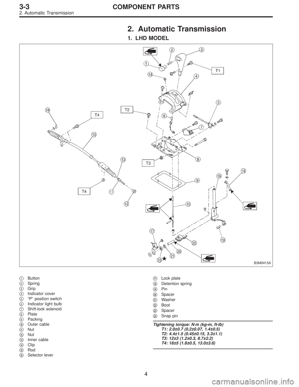
2. Automatic Transmission
1. LHD MODEL
B3M0415A
�1Button
�
2Spring
�
3Grip
�
4Indicator cover
�
5“P” position switch
�
6Indicator light bulb
�
7Shift-lock solenoid
�
8Plate
�
9Packing
�
10Outer cable
�
11Nut
�
12Nut
�
13Inner cable
�
14Clip
�
15Rod
�
16Selector lever�
17Lock plate
�
18Detention spring
�
19Pin
�
20Spacer
�
21Washer
�
22Boot
�
23Spacer
�
24Snap pin
Tightening torque: N⋅m (kg-m, ft-lb)
T1: 2.0±0.7 (0.2±0.07, 1.4±0.5)
T2: 4.4±1.5 (0.45±0.15, 3.3±1.1)
T3: 12±3 (1.2±0.3, 8.7±2.2)
T4: 18±5 (1.8±0.5, 13.0±3.6)
4
3-3COMPONENT PARTS
2. Automatic Transmission
Page 1028 of 3342
2. RHD MODEL
B3M0385A
�1Grip
�
2Spring
�
3Button
�
4Indicator cover
�
5“P”position switch
�
6Indicator light bulb
�
7Shift-lock solenoid
�
8Plate
�
9Packing
�
10Outer cable
�
11Nut
�
12Nut
�
13Inner cable
�
14Clip
�
15Rod�
16Selector lever
�
17Lock plate
�
18Detention spring
�
19Pin
�
20Spacer
�
21Washer
�
22Boot
�
23Spacer
�
24Snap pin
Tightening torque: N⋅m (kg-m, ft-lb)
T1: 4.4±1.5 (0.45±0.15, 3.3±1.1)
T2: 12±3 (1.2±0.3, 8.7±2.2)
T3: 18±5 (1.8±0.5, 13.0±3.6)
5
3-3COMPONENT PARTS
2. Automatic Transmission
Page 1036 of 3342
 Remove detention spring.
C: INSPECTION
1) Inspect removed parts by comparing with new ones for
deformation, damage and wear. Correct or replace if defec-
tive.
2) Confirm the following part")
G3M0709
8) Remove detention spring.
C: INSPECTION
1) Inspect removed parts by comparing with new ones for
deformation, damage and wear. Correct or replace if defec-
tive.
2) Confirm the following parts for operating condition
before assembly.
(1) Sliding condition of the button in the grip ... it should
move smoothly.
(2) Insertion of the grip on the selector lever ... when
pushing the grip on the selector lever by hand, screw
holes should be aligned.
(3) Operation of selector lever and rod ... they should
move smoothly.
(4) Insertion of the spacer into the selector lever ... it
should be inserted lightly by finger pressure.
G3M0707
D: ASSEMBLY
1) Clean all parts before assembly.
Apply grease [NIGLUBE-R or equivalent].
2) Assemble selector lever to the plate.
3) Insert the bolt and tighten the flange nut to the specified
torque.
Tightening torque (Flange nut):
12±3 N⋅m (1.2±0.3 kg-m, 8.7±2.2 ft-lb)
G3M0710
4) Assemble detention spring, shift-lock solenoid and“P”
position switch.
13
3-3SERVICE PROCEDURE
2. Automatic Transmission
Page 1039 of 3342
 After completion of fitting, make sure that the selector
lever operates smoothly all across the operating range.
11) Connect the harnesses and check the following items.
(1) The engine starts oper")
10) After completion of fitting, make sure that the selector
lever operates smoothly all across the operating range.
11) Connect the harnesses and check the following items.
(1) The engine starts operating when selector lever is
in position“P”, but not in other positions.
(2) The back-up light is lit when the selector lever is in
position“R”, but not in other positions.
B3M0348A
12) Check selector lever operation.
WARNING:
Stop the engine while checking operation of selector
lever.
(1) Check that selector lever does not move from“N”
to“R”without pushing the button.
(2) Check that selector lever does not move from“R”
to“P”without pushing the button.
(3) Check that selector lever does not move from“P”
to“R”without pushing the button and the brake pedal
depressed. [With ignition key set at“ON”.]
(4) Check that selector lever does not move from“3”to
“2”without pushing the button.
13) Check shift-lock system.
(1) Ensure ignition switch rotates from“ACC”to
“LOCK”when the selector lever is set at“P”. Also check
that ignition key can be removed from the“LOCK”posi-
tion only.
(2) Ensure selector lever moves from“P”to any other
position when the brake pedal is depressed with igni-
tion key set at“ON”or“START”.
16
3-3SERVICE PROCEDURE
2. Automatic Transmission
Page 1050 of 3342
G3M0031
5) Lightly tap the head of front propeller shaft with a cop-
per hammer until center bearing is removed.
CAUTION:
Be careful not to damage the thread portion.
D: INSPECTION
NOTE:
Do not disassemble propeller shaft. Check the following
and replace if necessary.
1) Tube surfaces for dents or cracks
2) Splines for deformation or abnormal wear
3) Joints for non-smooth operation or abnormal noise
4) Center bearing for free play, noise or non-smooth
operation
5) Oil seals for abnormal wear or damage
6) Center bearing for breakage
G3M0030
E: ASSEMBLY
1) Install center bearing onto front propeller shaft.
2) Align marks and install companion flange.
G3M0029
3) Tighten stake nut until center bearing is set in position.
CAUTION:
Be sure to install new stake nut.
Tightening torque:
270±25 N⋅m (27.5±2.5 kg-m, 199±18 ft-lb)
NOTE:
Stake the nut after tightening.
12
3-4SERVICE PROCEDURE
1. Propeller Shaft
 Remove the oil pump cover.
NOTE:
Lightly tap the end of the stator shaft to remove the cover.
G3M0447
3) Remove the retainer and return spring. Then remove
the rotor, two vane rings and nin")

 Lightly tap the head of front propeller shaft with a cop-
per hammer until center bearing is removed.
CAUTION:
Be careful not to damage the thread portion.
D: INSPECTION
NOTE:
Do not disass")