Page 648 of 3342
 The following job should be followed before disassem-
bly:
(1) Clean oil, grease, dirt and dust from transmission.
(2) Remove drain plug�
1to drain oil. After draining,
reti")
B3M0037A
B: PRECAUTIONS
1) The following job should be followed before disassem-
bly:
(1) Clean oil, grease, dirt and dust from transmission.
(2) Remove drain plug�
1to drain oil. After draining,
retighten it as before.
CAUTION:
Replace gasket with a new one.
Tightening torque:
44±3 N⋅m (4.5±0.3 kg-m, 32.5±2.2 ft-lb)
G3M0517
(3) Attach transmission to ST.
ST 499937100 TRANSMISSION STAND SET
2) Rotating parts should be coated with oil prior to assem-
bly.
3) All disassembled parts, if to be reused, should be rein-
stalled in the original positions and directions.
4) Gaskets and lock washers must be replaced with new
ones.
5) Liquid gasket should be used where specified to pre-
vent leakage.
6) Fill transmission gear oil through the oil level gauge
hole up to upper point level gauge.
C: INSPECTION
Disassembled parts should be washed clean first and then
inspected carefully.
1) Bearings
Replace bearings in the following cases:
�Bearings whose balls, outer races and inner races are
broken or rusty.
�Worn bearings
�Bearings that fail to turn smoothly or make abnormal
noise when turned after gear oil lubrication.
B3M0038A
The ball bearing�3on the rear side of the drive pinion shaft
�
2should be checked for smooth rotation before the drive
pinion assembly is disassembled. In this case, because a
preload is working on the bearing, its rotation feels like it is
slightly dragging unlike the other bearings.
�Bearings having other defects
16
3-1SERVICE PROCEDURE
1. General
Page 653 of 3342
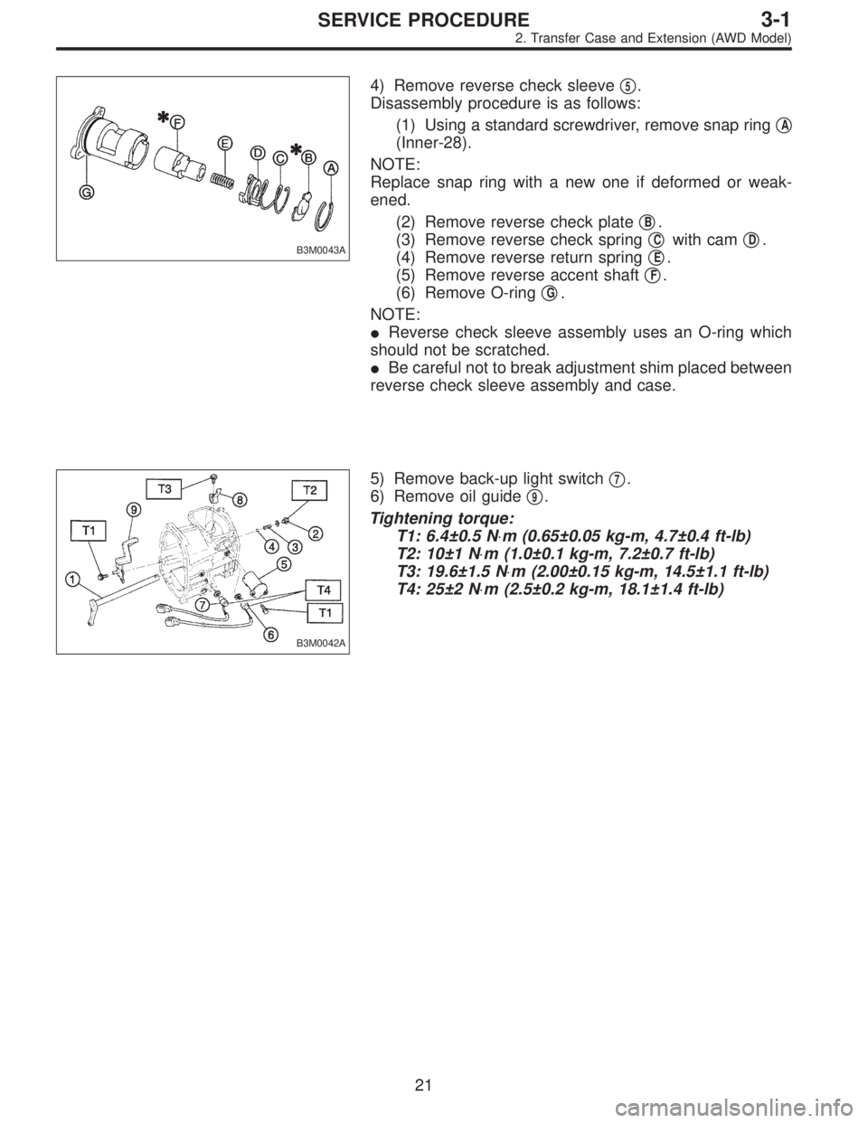
B3M0043A
4) Remove reverse check sleeve�5.
Disassembly procedure is as follows:
(1) Using a standard screwdriver, remove snap ring�
A
(Inner-28).
NOTE:
Replace snap ring with a new one if deformed or weak-
ened.
(2) Remove reverse check plate�
B.
(3) Remove reverse check spring�
Cwith cam�D.
(4) Remove reverse return spring�
E.
(5) Remove reverse accent shaft�
F.
(6) Remove O-ring�
G.
NOTE:
�Reverse check sleeve assembly uses an O-ring which
should not be scratched.
�Be careful not to break adjustment shim placed between
reverse check sleeve assembly and case.
B3M0042A
5) Remove back-up light switch�7.
6) Remove oil guide�
9.
Tightening torque:
T1: 6.4±0.5 N⋅m (0.65±0.05 kg-m, 4.7±0.4 ft-lb)
T2: 10±1 N⋅m (1.0±0.1 kg-m, 7.2±0.7 ft-lb)
T3: 19.6±1.5 N⋅m (2.00±0.15 kg-m, 14.5±1.1 ft-lb)
T4: 25±2 N⋅m (2.5±0.2 kg-m, 18.1±1.4 ft-lb)
21
3-1SERVICE PROCEDURE
2. Transfer Case and Extension (AWD Model)
Page 660 of 3342

T1: 15.7±1.5 (1.6±0.15, 11.6±1.1)
T2: 19.6±1.5 (2.00±0.15, 14.5±1.1)
T3: 24.5±2.0 (2.50±0.20, 18.1±1.4)
1) Install transfer cas")
D: INSTALLATION
B3M0053A
Tightening torque: N⋅m (kg-m, ft-lb)
T1: 15.7±1.5 (1.6±0.15, 11.6±1.1)
T2: 19.6±1.5 (2.00±0.15, 14.5±1.1)
T3: 24.5±2.0 (2.50±0.20, 18.1±1.4)
1) Install transfer case�2with extension assembly�1.
2) Secure selector arm to shifter arm with shifter fork
screw�
3. Shifter arm should be caught by pawl of rod.
Selector arm must be engaged with reverse check sleeve
assembly.
3) Adjustment of neutral position
(1) Shift gear into 3rd gear position.
(2) Shifter arm turns lightly toward the 1st/2nd gear
side but heavily toward the reverse gear side because
of the function of the return spring, until arm contacts
the stopper.
(3) Make adjustment so that the heavy stroke (reverse
side) is a little more than the light stroke (1st/2nd side).
(4) To adjust, remove bolts holding reverse check
sleeve assembly�
4to the case, move sleeve assem-
bly outward, and place adjustment shim (0 to 1 ea.)
between sleeve assembly and case to adjust the clear-
ance.
28
3-1SERVICE PROCEDURE
2. Transfer Case and Extension (AWD Model)
Page 662 of 3342
3. Rear Case (FWD Model)
A: DISASSEMBLY
G3M0952
Tightening torque: N⋅m (kg-m, ft-lb)
T1: 6.4±0.5 (0.65±0.05, 4.7±0.4)
T2: 10±1 (1.0±0.1, 7.2±0.7)
T3: 25±2 (2.5±0.2, 18.1±1.4)
1) Remove rear case�1.
2) Remove plug�
2, spring�3and reverse check ball�4.
3) Remove neutral switch�
5.
4) Pull out shifter arm�
6.
5) Remove reverse check sleeve�
7.
NOTE:
The disassembly procedure is the same as for AWD model.
B3M0056A
6) Remove back-up light switch�8.
7) Remove oil seal�
9.
CAUTION:
Do not reuse oil seal.
30
3-1SERVICE PROCEDURE
3. Rear Case (FWD Model)
Page 663 of 3342
 Assembly of rear case is in the reverse order of disas-
sembly.
G3M0952
Tightening torque: N⋅m (kg-m, ft-lb)
T1: 6.4±0.5 (0.65±0.05, 4.7±0.4)
T2: 10±1 (1.0±0.1, 7.2±0.7)
T3: 25�")
B: ASSEMBLY
1) Assembly of rear case is in the reverse order of disas-
sembly.
G3M0952
Tightening torque: N⋅m (kg-m, ft-lb)
T1: 6.4±0.5 (0.65±0.05, 4.7±0.4)
T2: 10±1 (1.0±0.1, 7.2±0.7)
T3: 25±5 (2.5±0.5, 18.1±3.6)
2) Installation of shifter arm�6
Install shifter arm into the partition from the front while
inserting selector arm into the opening in reverse check
sleeve. Pass shaft through hole in selector arm until its end
comes out of the rear of transmission case assembly.
CAUTION:
Apply a coat of gear oil to shifter arm. Also make sure
oil seal is positioned properly.
3) Adjustment of neutral position
NOTE:
After assembling and installing rear case, adjust neutral
position.
(1) Shift gear into 3rd gear position.
(2) Shifter arm turns lightly toward the 1st/2nd gear
side but heavily toward the reverse gear side because
of the function of the return spring, until arm contacts
the stopper.
(3) Make adjustment so that the heavy stroke (reverse
side) is a little more than the light stroke (1st/2nd side).
(4) To adjust, remove bolts holding reverse check
sleeve assembly to the case, move sleeve assembly
outward, and place adjustment shim (0 to 1 ea.)
between sleeve assembly and case to adjust the clear-
ance.
31
3-1SERVICE PROCEDURE
3. Rear Case (FWD Model)
Page 678 of 3342
 Place the transmission with case left side facing
downward and put ST1 on bearing cup.
(2) Screw retainer assembly into left case from the bot-
tom with ST2. Fit ST3 on the transmission ma")
G3M0564
(1) Place the transmission with case left side facing
downward and put ST1 on bearing cup.
(2) Screw retainer assembly into left case from the bot-
tom with ST2. Fit ST3 on the transmission main shaft.
Shift gear into 4th or 5th and turn the shaft several
times. Screw in the retainer while turning ST3 until a
slight resistance is felt on ST2.
This is the contact point of hypoid gear and drive pin-
ion shaft. Repeat the above sequence several times to
ensure the contact point.
ST1 399780104 WEIGHT
ST2 499787000 WRENCH ASSY
ST3 499927100 HANDLE
B3M0340A
(3) Remove weight and screw in retainer without
O-ring on the upper side and stop at the point where
slight resistance is felt.
NOTE:
At this point, the backlash between the hypoid gear and
drive pinion shaft is zero.
ST 499787000 WRENCH ASSY
B3M0334A
(4) Fit lock plate�11. Loosen the retainer on the lower
side by 1-1/2 notches of lock plate and turn in the
retainer on the upper side by the same amount in order
to obtain the backlash.
NOTE:
The notch on the lock plate moves by 1/2 notch if the plate
is turned upside down.
(5) Turn in the retainer on the upper side additionally
by 1 notch in order to apply preload on taper roller
bearing.
(6) Tighten temporarily both the upper and lower lock
plates and mark both holder and lock plate for later
readjustment.
(7) Turn transmission main shaft several times while
tapping around retainer lightly with plastic hammer.
(8) Set ST1 and ST2. Insert the needle through trans-
mission oil drain plug hole so that the needle comes in
contact with the tooth surface at a right angle and check
the backlash.
46
3-1SERVICE PROCEDURE
4. Transmission Case
Page 681 of 3342
 Selecting of main shaft rear plate
Using ST, measure the amount A of ball bearing protrusion
from transmission main case surface and select the proper
plate in the following table:
ST 4981")
G3M0573
12) Selecting of main shaft rear plate
Using ST, measure the amount A of ball bearing protrusion
from transmission main case surface and select the proper
plate in the following table:
ST 498147000 DEPTH GAUGE
Dimension“A”
mm (in)Part No. Mark
4.00—4.13
(0.1575—0.1626)32294AA041 1
3.87—3.99
(0.1524—0.1571)32294AA051 2
NOTE:
Before measuring, tap the end of main shaft with a plastic
hammer lightly in order to make the clearance zero
between the main case surface and the moving flange of
bearing.
B3M0336D
13) Install clutch release lever�1and operating cylinder
(hydraulic application type)�
2.
[W3C2], [W5A0].>
G3M0595
5. Drive Pinion Assembly (AWD Model)
A: DISASSEMBLY
1. DRIVE PINION SHAFT
1) Straighten lock nut at staked portion. Remove the lock
nut using ST1, ST2 and ST3.
ST1 899884100 HOLDER
ST2 498427100 STOPPER
ST3 899988608 SOCKET WRENCH
G3M0606
2) Withdraw drive pinion from driven shaft.
Remove differential bevel gear sleeve�
1, adjusting washer
No. 1�
2(25 x 37.5 x t), adjusting washer No. 2�3(25 x
37.5 x 4), thrust bearing�
4(25 x 37.5 x 3), needle bearing
�
5(25 x 30 x 20), drive pinion collar�6, needle bearing�7
(30 x 37 x 23) and thrust bearing�8(33x50x3).
49
3-1SERVICE PROCEDURE
5. Drive Pinion Assembly (AWD Model)
Page 682 of 3342
 Selecting of main shaft rear plate
Using ST, measure the amount A of ball bearing protrusion
from transmission main case surface and select the proper
plate in the following table:
ST 4981")
G3M0573
12) Selecting of main shaft rear plate
Using ST, measure the amount A of ball bearing protrusion
from transmission main case surface and select the proper
plate in the following table:
ST 498147000 DEPTH GAUGE
Dimension“A”
mm (in)Part No. Mark
4.00—4.13
(0.1575—0.1626)32294AA041 1
3.87—3.99
(0.1524—0.1571)32294AA051 2
NOTE:
Before measuring, tap the end of main shaft with a plastic
hammer lightly in order to make the clearance zero
between the main case surface and the moving flange of
bearing.
B3M0336D
13) Install clutch release lever�1and operating cylinder
(hydraulic application type)�
2.
[W3C2], [W5A0].>
G3M0595
5. Drive Pinion Assembly (AWD Model)
A: DISASSEMBLY
1. DRIVE PINION SHAFT
1) Straighten lock nut at staked portion. Remove the lock
nut using ST1, ST2 and ST3.
ST1 899884100 HOLDER
ST2 498427100 STOPPER
ST3 899988608 SOCKET WRENCH
G3M0606
2) Withdraw drive pinion from driven shaft.
Remove differential bevel gear sleeve�
1, adjusting washer
No. 1�
2(25 x 37.5 x t), adjusting washer No. 2�3(25 x
37.5 x 4), thrust bearing�
4(25 x 37.5 x 3), needle bearing
�
5(25 x 30 x 20), drive pinion collar�6, needle bearing�7
(30 x 37 x 23) and thrust bearing�8(33x50x3).
49
3-1SERVICE PROCEDURE
5. Drive Pinion Assembly (AWD Model)

A: DISASSEMBLY
G3M0952
Tightening torque: N⋅m (kg-m, ft-lb)
T1: 6.4±0.5 (0.65±0.05, 4.7±0.4)
T2: 10±1 (1.0±0.1, 7.2±0.7)
T3: 25±2 (2.5±0.2, 18.1±1.4)
1) Remove rear")