Page 574 of 3342
 While pushing release lever�
3to pivot and twisting it to
both sides, fit retainer spring�
5onto the constricted portion
of pivot.
NOTE:
Confirm that retaine")
B2M0633A
1. MECHANICAL APPLICATION TYPE
1) While pushing release lever�
3to pivot and twisting it to
both sides, fit retainer spring�
5onto the constricted portion
of pivot.
NOTE:
Confirm that retainer spring is securely fitted by observing
it through the main case hole.
2) Install release bearing�
6and fasten it with two clips�2.
3) Install release lever seal�
4.
G2M0235
4) After remounting engine and transmission on body,
make adjustment of the clutch release lever end play.
CAUTION:
Take care not to twist the cable during adjustment.
5) Install release lever return spring (Models without hill
holder only).
NOTE:
Hook up the return spring to right side hole of the release
lever.
B2M1257C
2. HYDRAULIC APPLICATION TYPE
1) While pushing release lever�
1to pivot and twisting it to
both sides, fit retainer spring�
2onto the constricted portion
of pivot.
NOTE:
�Apply grease (SUNLIGHT 2: P/N 003602010) to contact
point of release lever and operating cylinder.
�Confirm that retainer spring is securely fitted by observ-
ing it through the main case hole.
2) Install release bearing�
3and fasten it with two clips�4.
3) Install release lever seal�
5.
4) Install operating cylinder�
6.
Tightening torque:
T: 37±3 N⋅m (3.8±0.3 kg-m, 27.5±2.2 ft-lb)
11
2-10SERVICE PROCEDURE
3. Release Bearing and Lever
Page 581 of 3342
B2M1179C
4) Installation is in the reverse order of removal.
NOTE:
Before installing operating cylinder, apply grease (SUN-
LIGHT 2: P/N 003602010) to contact point of release lever
and operating cylinder.
Tightening torque:
T1: 18±3 N⋅m (1.8±0.3 kg-m, 13.0±2.2 ft-lb)
T2: 37±3 N⋅m (3.8±0.3 kg-m, 27.5±2.2 ft-lb)
5) After bleeding air from operating cylinder, ensure that
clutch operates properly.
G2M0979
6. Master Cylinder and Reservoir Tank
A: REMOVAL
1) Remove snap pin�2, clevis pin�1and separate push
rod�
3of master cylinder from clutch pedal.
B2M1260A
2) Remove clutch hose from master cylinder.
CAUTION:
Plug up hose connection to prevent clutch fluid from
spilling out.
B2M1261A
3) Remove master cylinder with reservoir tank.
16
2-10SERVICE PROCEDURE
5. Operating Cylinder - 6. Master Cylinder and Reservoir Tank
Page 582 of 3342
B2M1179C
4) Installation is in the reverse order of removal.
NOTE:
Before installing operating cylinder, apply grease (SUN-
LIGHT 2: P/N 003602010) to contact point of release lever
and operating cylinder.
Tightening torque:
T1: 18±3 N⋅m (1.8±0.3 kg-m, 13.0±2.2 ft-lb)
T2: 37±3 N⋅m (3.8±0.3 kg-m, 27.5±2.2 ft-lb)
5) After bleeding air from operating cylinder, ensure that
clutch operates properly.
G2M0979
6. Master Cylinder and Reservoir Tank
A: REMOVAL
1) Remove snap pin�2, clevis pin�1and separate push
rod�
3of master cylinder from clutch pedal.
B2M1260A
2) Remove clutch hose from master cylinder.
CAUTION:
Plug up hose connection to prevent clutch fluid from
spilling out.
B2M1261A
3) Remove master cylinder with reservoir tank.
16
2-10SERVICE PROCEDURE
5. Operating Cylinder - 6. Master Cylinder and Reservoir Tank
Page 607 of 3342
G2M0299
20) Remove bolts which hold upper side of transmission to
engine.
G2M0300
21) Remove engine from vehicle.
(1) Slightly raise engine.
(2) Raise transmission with garage jack.
(3) Move engine horizontally until mainshaft is with-
drawn from clutch cover.
(4) Slowly move engine away from engine compart-
ment.
CAUTION:
Be careful not to damage adjacent parts or body pan-
els with crank pulley, oil pressure gauge, etc.
19
2-11SERVICE PROCEDURE
2. Engine
Page 617 of 3342
B2M1170
1) Open front hood fully, and support with stay.
2) Disconnect battery ground terminal.
3) Remove air intake duct and chamber.
G2M0544
4) Disconnect connectors and cables.
(1) Disconnect the following connectors.
�Front oxygen sensor connector
G2M0307
�Transmission harness connector
�Transmission ground terminal
B2M0337
�Neutral position switch connector (MT model)
�Back-up light switch connector (MT model)
G2M0827
�Vehicle speed sensor 2
29
2-11SERVICE PROCEDURE
3. Transmission
Page 633 of 3342
20) Connect connectors and cables.
(1) Connect the following connectors.
�Transmission harness connectors
�Transmission ground terminal
�Front oxygen sensor connector
�Vehicle speed sensor 2
�Neutral position switch connector (MT model)
�Back-up light switch connector (MT model)
(2) Connect the following cables.
�Cruise control cable
(With cruise control model)
�Clutch cable
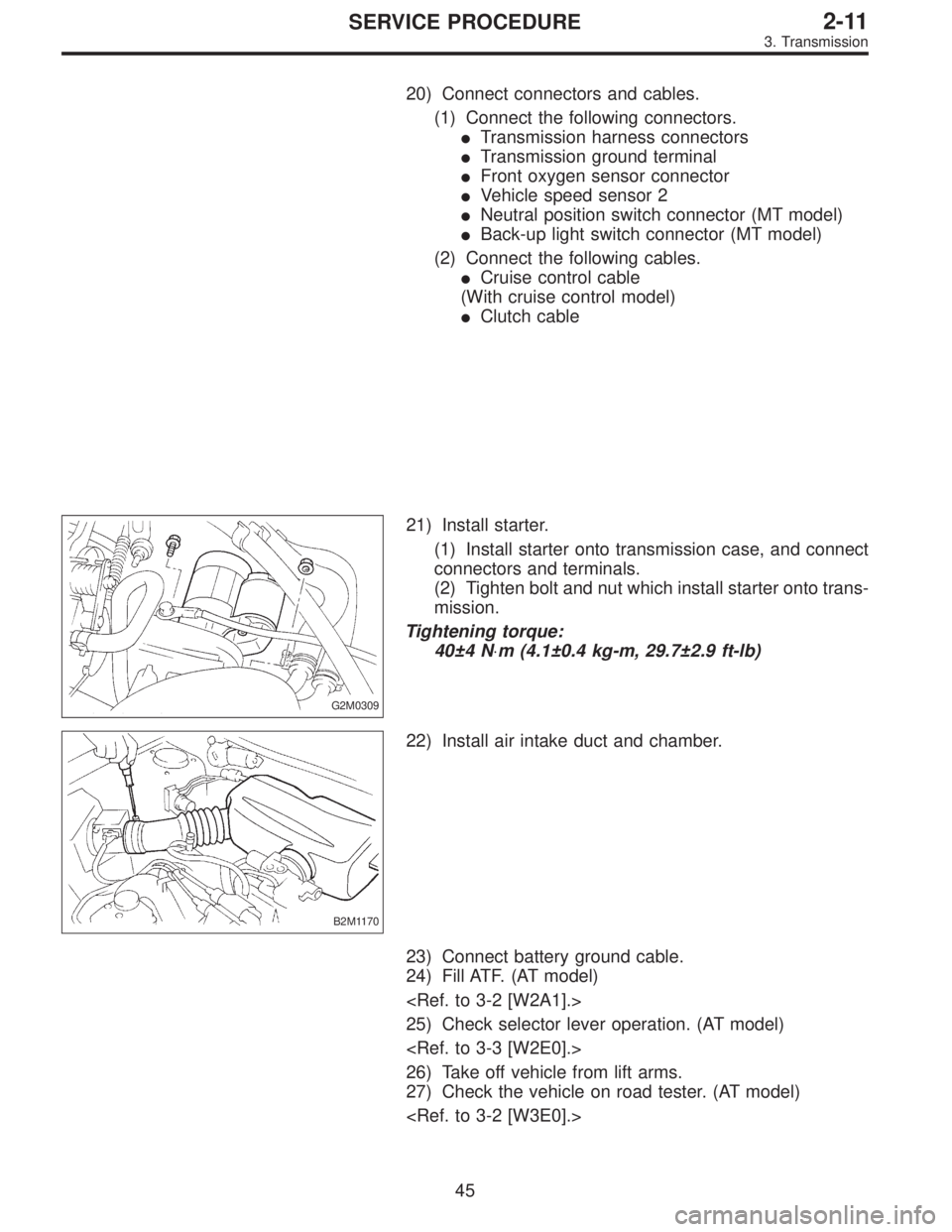
G2M0309
21) Install starter.
(1) Install starter onto transmission case, and connect
connectors and terminals.
(2) Tighten bolt and nut which install starter onto trans-
mission.
Tightening torque:
40±4 N⋅m (4.1±0.4 kg-m, 29.7±2.9 ft-lb)
B2M1170
22) Install air intake duct and chamber.
23) Connect battery ground cable.
24) Fill ATF. (AT model)
25) Check selector lever operation. (AT model)
26) Take off vehicle from lift arms.
27) Check the vehicle on road tester. (AT model)
45
2-11SERVICE PROCEDURE
3. Transmission
Page 638 of 3342
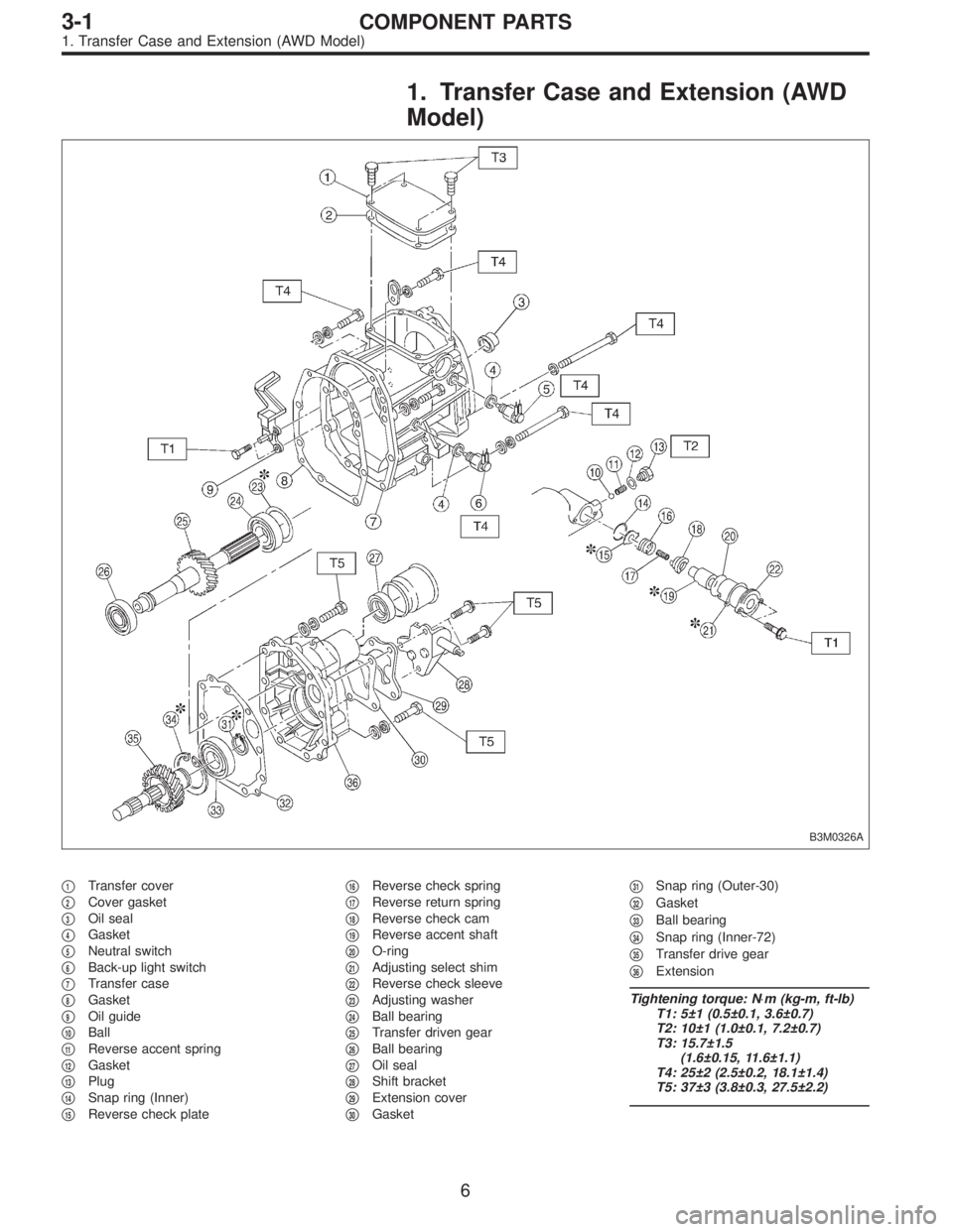
1. Transfer Case and Extension (AWD
Model)
B3M0326A
�1Transfer cover
�
2Cover gasket
�
3Oil seal
�
4Gasket
�
5Neutral switch
�
6Back-up light switch
�
7Transfer case
�
8Gasket
�
9Oil guide
�
10Ball
�
11Reverse accent spring
�
12Gasket
�
13Plug
�
14Snap ring (Inner)
�
15Reverse check plate�
16Reverse check spring
�
17Reverse return spring
�
18Reverse check cam
�
19Reverse accent shaft
�
20O-ring
�
21Adjusting select shim
�
22Reverse check sleeve
�
23Adjusting washer
�
24Ball bearing
�
25Transfer driven gear
�
26Ball bearing
�
27Oil seal
�
28Shift bracket
�
29Extension cover
�
30Gasket�
31Snap ring (Outer-30)
�
32Gasket
�
33Ball bearing
�
34Snap ring (Inner-72)
�
35Transfer drive gear
�
36Extension
Tightening torque: N⋅m (kg-m, ft-lb)
T1: 5±1 (0.5±0.1, 3.6±0.7)
T2: 10±1 (1.0±0.1, 7.2±0.7)
T3: 15.7±1.5
(1.6±0.15, 11.6±1.1)
T4: 25±2 (2.5±0.2, 18.1±1.4)
T5: 37±3 (3.8±0.3, 27.5±2.2)
6
3-1COMPONENT PARTS
1. Transfer Case and Extension (AWD Model)
Page 639 of 3342
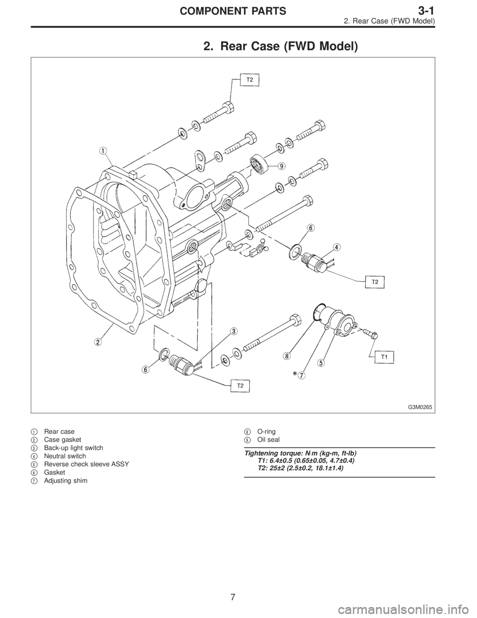
2. Rear Case (FWD Model)
G3M0265
�1Rear case
�
2Case gasket
�
3Back-up light switch
�
4Neutral switch
�
5Reverse check sleeve ASSY
�
6Gasket
�
7Adjusting shim�
8O-ring
�
9Oil seal
Tightening torque: N⋅m (kg-m, ft-lb)
T1: 6.4±0.5 (0.65±0.05, 4.7±0.4)
T2: 25±2 (2.5±0.2, 18.1±1.4)
7
3-1COMPONENT PARTS
2. Rear Case (FWD Model)
 Installation is in the reverse order of removal.
NOTE:
Before installing operating cylinder, apply grease (SUN-
LIGHT 2: P/N 003602010) to contact point of release lever
and operating cyli")
 Installation is in the reverse order of removal.
NOTE:
Before installing operating cylinder, apply grease (SUN-
LIGHT 2: P/N 003602010) to contact point of release lever
and operating cyli")
 Remove bolts which hold upper side of transmission to
engine.
G2M0300
21) Remove engine from vehicle.
(1) Slightly raise engine.
(2) Raise transmission with garage jack.
(3) Move engine ho")
 Open front hood fully, and support with stay.
2) Disconnect battery ground terminal.
3) Remove air intake duct and chamber.
G2M0544
4) Disconnect connectors and cables.
(1) Disconnect the f")