Page 282 of 3342
B: INSPECTION
1. TIMING BELT
1) Check timing belt teeth for breaks, cracks, and wear. If
any fault is found, replace belt.
2) Check the condition of back side of belt; if any crack is
found, replace belt.
CAUTION:
�Be careful not to let oil, grease or coolant contact
the belt. Remove quickly and thoroughly if this hap-
pens.
G2M0115
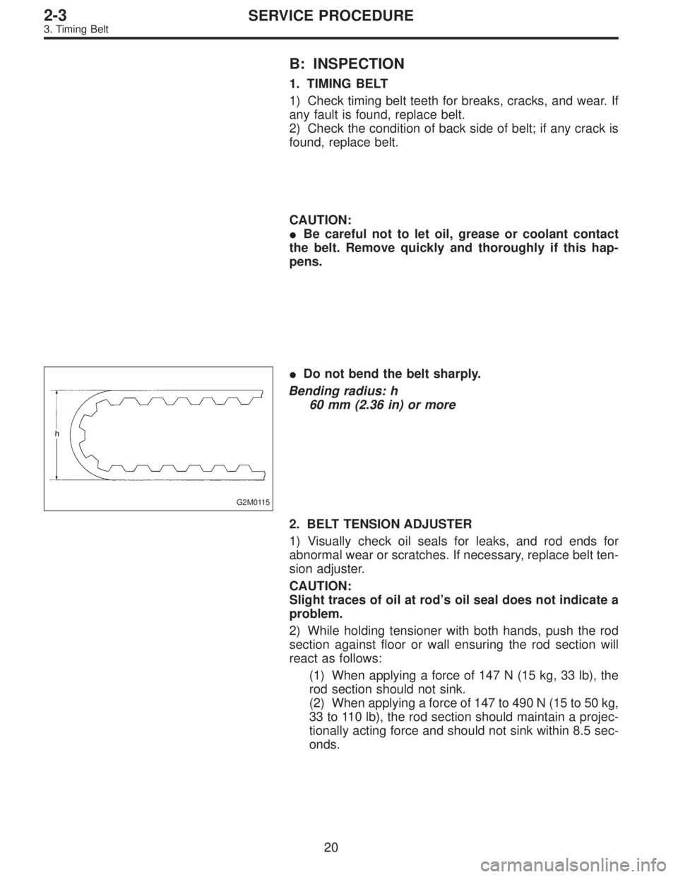
�Do not bend the belt sharply.
Bending radius: h
60 mm (2.36 in) or more
2. BELT TENSION ADJUSTER
1) Visually check oil seals for leaks, and rod ends for
abnormal wear or scratches. If necessary, replace belt ten-
sion adjuster.
CAUTION:
Slight traces of oil at rod’s oil seal does not indicate a
problem.
2) While holding tensioner with both hands, push the rod
section against floor or wall ensuring the rod section will
react as follows:
(1) When applying a force of 147 N (15 kg, 33 lb), the
rod section should not sink.
(2) When applying a force of 147 to 490 N (15 to 50 kg,
33 to 110 lb), the rod section should maintain a projec-
tionally acting force and should not sink within 8.5 sec-
onds.
20
2-3SERVICE PROCEDURE
3. Timing Belt
Page 306 of 3342
B2M0077A
(6) Check the valve guide protrusion.
Valve guide protrusion: L
17.5—18.0 mm (0.689—0.709 in)
B2M0078
(7) Ream the inside of valve guide with ST. Gently
rotate the reamer clockwise while pressing it lightly into
valve guide, and return it also rotating clockwise. After
reaming, clean valve guide to remove chips.
ST 499767400 VALVE GUIDE REAMER
CAUTION:
�Apply engine oil to the reamer when reaming.
�If the inner surface of the valve guide is torn, the
edge of the reamer should be slightly ground with an
oil stone.
�If the inner surface of the valve guide becomes lus-
trous and the reamer does not chips, use a new reamer
or remedy the reamer.
(8) Recheck the contact condition between valve and
valve seat after replacing valve guide.
43
2-3SERVICE PROCEDURE
6. Cylinder Head
Page 310 of 3342
B2M0386A
(3) Install valve spring and retainer.
CAUTION:
Be sure to install the valve springs with their painted
facing towards the valve spring retainer.
(4) Set ST on valve spring.
ST 499718000 VALVE SPRING REMOVER
(5) Compress valve spring and fit valve spring retainer
key.
B2M1210A
(6) After installing, tap valve spring retainers lightly
with wooden hammer for better seating.
3) Install camshaft and support.
4) Install valve rocker assembly.
5) Install rocker cover.
47
2-3SERVICE PROCEDURE
6. Cylinder Head
Page 322 of 3342
B2M0084A
B2M0420A
4) Check circlip installation groove on the piston for burr.
If necessary, remove burr from the groove so that piston
pin can lightly move.
5) Check piston pin circlip for distortion, cracks and wear.
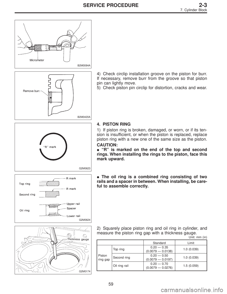
G2M0623
4. PISTON RING
1) If piston ring is broken, damaged, or worn, or if its ten-
sion is insufficient, or when the piston is replaced, replace
piston ring with a new one of the same size as the piston.
CAUTION:
�“R”is marked on the end of the top and second
rings. When installing the rings to the piston, face this
mark upward.
G2M0624
�The oil ring is a combined ring consisting of two
rails and a spacer in between. When installing, be care-
ful to assemble correctly.
G2M0174
2) Squarely place piston ring and oil ring in cylinder, and
measure the piston ring gap with a thickness gauge.
Unit: mm (in)
Standard Limit
Piston
ring gapTop ring0.20—0.35
(0.0079—0.0138)1.0 (0.039)
Second ring0.20—0.50
(0.0079—0.0197)1.0 (0.039)
Oil ring rail0.20—0.70
(0.0079—0.0276)1.5 (0.059)
59
2-3SERVICE PROCEDURE
7. Cylinder Block
Page 341 of 3342
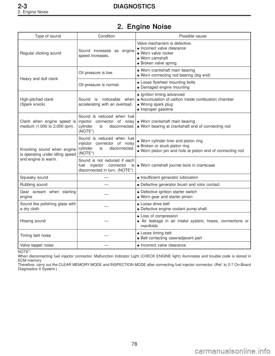
2. Engine Noise
Type of sound Condition Possible cause
Regular clicking soundSound increases as engine
speed increases.Valve mechanism is defective.
�Incorrect valve clearance
�Worn valve rocker
�Worn camshaft
�Broken valve spring
Heavy and dull clankOil pressure is low.�Worn crankshaft main bearing
�Worn connecting rod bearing (big end)
Oil pressure is normal.�Loose flywheel mounting bolts
�Damaged engine mounting
High-pitched clank
(Spark knock)Sound is noticeable when
accelerating with an overload.�Ignition timing advanced
�Accumulation of carbon inside combustion chamber
�Wrong spark plug
�Improper gasoline
Clank when engine speed is
medium (1,000 to 2,000 rpm).Sound is reduced when fuel
injector connector of noisy
cylinder is disconnected.
(NOTE*)�Worn crankshaft main bearing
�Worn bearing at crankshaft end of connecting rod
Knocking sound when engine
is operating under idling speed
and engine is warm.Sound is reduced when fuel
injector connector of noisy
cylinder is disconnected.
(NOTE*)�Worn cylinder liner and piston ring
�Broken or stuck piston ring
�Worn piston pin and hole at piston end of connecting rod
Sound is not reduced if each
fuel injector connector is
disconnected in turn. (NOTE*)�Worn camshaft journal bore in crankcase
Squeaky sound—�Insufficient generator lubrication
Rubbing sound—�Defective generator brush and rotor contact
Gear scream when starting
engine—�Defective ignition starter switch
�Worn gear and starter pinion
Sound like polishing glass with
a dry cloth—�Loose drive belt
�Defective engine coolant pump shaft
Hissing sound—�Loss of compression
�Air leakage in air intake system, hoses, connections or
manifolds
Timing belt noise—�Loose timing belt
�Belt contacting case/adjacent part
Valve tappet noise—�Incorrect valve clearance
NOTE*:
When disconnecting fuel injector connector, Malfunction Indicator Light (CHECK ENGINE light) illuminates and trouble code is stored in
ECM memory.
Therefore, carry out the CLEAR MEMORY MODE and INSPECTION MODE after connecting fuel injector connector. (Ref. to 2-7 On-Board
Diagnostics II System.)
78
2-3DIAGNOSTICS
2. Engine Noise
Page 360 of 3342
2. BELT TENSION ADJUSTER
1) Visually check oil seals for leaks, and rod ends for
abnormal wear or scratches. If necessary, replace belt ten-
sion adjuster.
CAUTION:
Slight traces of oil at rod’s oil seal does not indicate a
problem.
2) While holding tensioner with both hands, push the rod
section against floor or wall ensuring the rod section will
react as follows:
(1) When applying a force of 147 N (15 kg, 33 lb), the
rod section should not sink.
(2) When applying a force of 147 to 490 N (15 to 50 kg,
33 to 110 lb), the rod section should maintain a projec-
tionally acting force and should not sink within 8.5 sec-
onds.
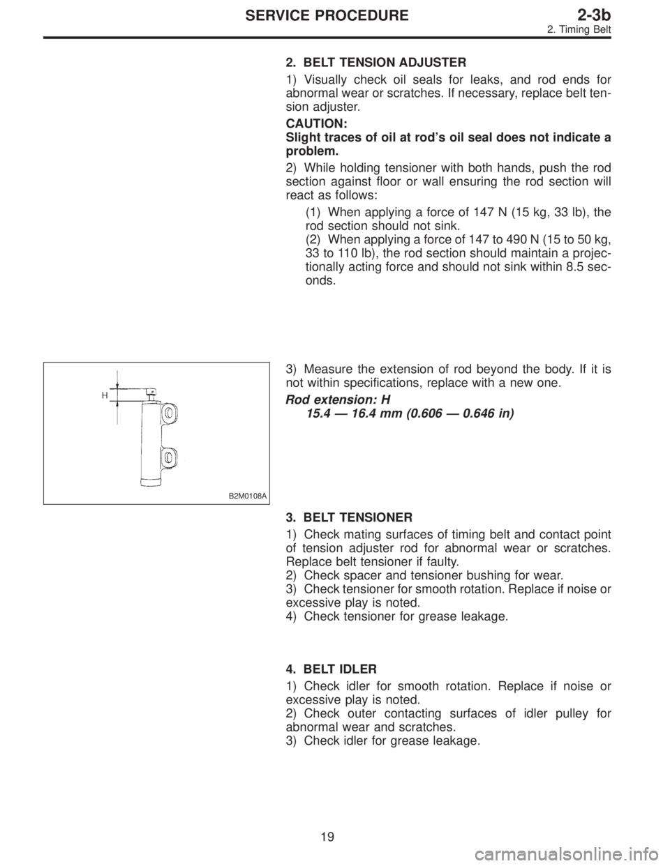
B2M0108A
3) Measure the extension of rod beyond the body. If it is
not within specifications, replace with a new one.
Rod extension: H
15.4 — 16.4 mm (0.606 — 0.646 in)
3. BELT TENSIONER
1) Check mating surfaces of timing belt and contact point
of tension adjuster rod for abnormal wear or scratches.
Replace belt tensioner if faulty.
2) Check spacer and tensioner bushing for wear.
3) Check tensioner for smooth rotation. Replace if noise or
excessive play is noted.
4) Check tensioner for grease leakage.
4. BELT IDLER
1) Check idler for smooth rotation. Replace if noise or
excessive play is noted.
2) Check outer contacting surfaces of idler pulley for
abnormal wear and scratches.
3) Check idler for grease leakage.
19
2-3bSERVICE PROCEDURE
2. Timing Belt
Page 375 of 3342
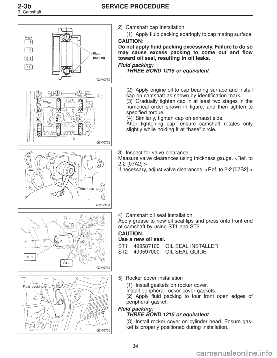
G2M0752
2) Camshaft cap installation
(1) Apply fluid packing sparingly to cap mating surface.
CAUTION:
Do not apply fluid packing excessively. Failure to do so
may cause excess packing to come out and flow
toward oil seal, resulting in oil leaks.
Fluid packing:
THREE BOND 1215 or equivalent
G2M0753
(2) Apply engine oil to cap bearing surface and install
cap on camshaft as shown by identification mark.
(3) Gradually tighten cap in at least two stages in the
numerical order shown in figure, and then tighten to
specified torque.
(4) Similarly, tighten cap on exhaust side.
After tightening cap, ensure camshaft rotates only
slightly while holding it at“base”circle.
B2M1219A
3) Inspect for valve clearance.
Measure valve clearances using thickness gauge.
2-2 [07A2].>
If necessary, adjust valve clearances.
G2M0754
4) Camshaft oil seal installation
Apply grease to new oil seal lips and press onto front end
of camshaft by using ST1 and ST2.
CAUTION:
Use a new oil seal.
ST1 499587100 OIL SEAL INSTALLER
ST2 499597000 OIL SEAL GUIDE
G2M0755
5) Rocker cover installation
(1) Install gaskets on rocker cover.
Install peripheral rocker cover gaskets.
(2) Apply fluid packing to four front open edges of
peripheral gasket.
Fluid packing:
THREE BOND 1215 or equivalent
(3) Install rocker cover on cylinder head. Ensure gas-
ket is properly positioned during installation.
34
2-3bSERVICE PROCEDURE
3. Camshaft
Page 381 of 3342
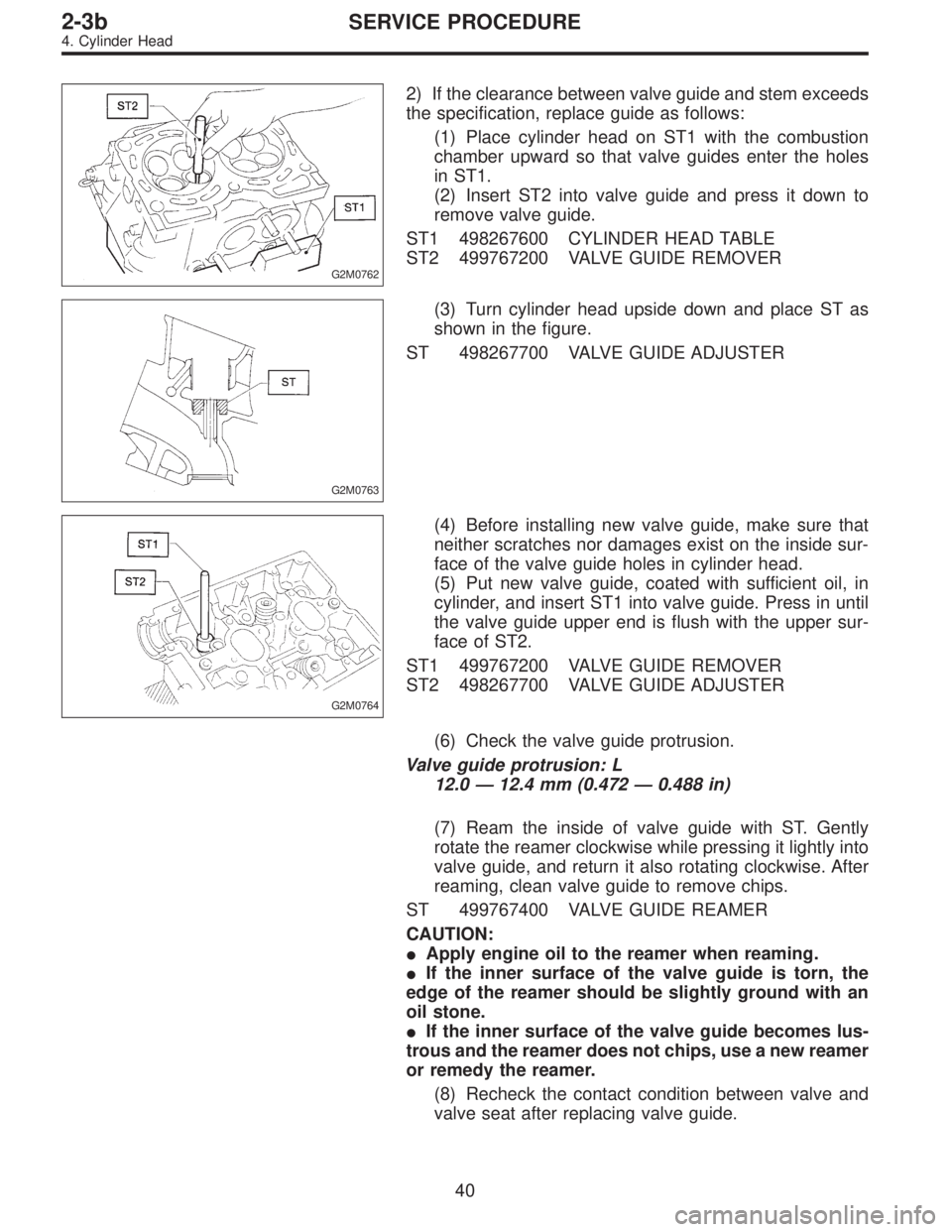
G2M0762
2) If the clearance between valve guide and stem exceeds
the specification, replace guide as follows:
(1) Place cylinder head on ST1 with the combustion
chamber upward so that valve guides enter the holes
in ST1.
(2) Insert ST2 into valve guide and press it down to
remove valve guide.
ST1 498267600 CYLINDER HEAD TABLE
ST2 499767200 VALVE GUIDE REMOVER
G2M0763
(3) Turn cylinder head upside down and place ST as
shown in the figure.
ST 498267700 VALVE GUIDE ADJUSTER
G2M0764
(4) Before installing new valve guide, make sure that
neither scratches nor damages exist on the inside sur-
face of the valve guide holes in cylinder head.
(5) Put new valve guide, coated with sufficient oil, in
cylinder, and insert ST1 into valve guide. Press in until
the valve guide upper end is flush with the upper sur-
face of ST2.
ST1 499767200 VALVE GUIDE REMOVER
ST2 498267700 VALVE GUIDE ADJUSTER
(6) Check the valve guide protrusion.
Valve guide protrusion: L
12.0—12.4 mm (0.472—0.488 in)
(7) Ream the inside of valve guide with ST. Gently
rotate the reamer clockwise while pressing it lightly into
valve guide, and return it also rotating clockwise. After
reaming, clean valve guide to remove chips.
ST 499767400 VALVE GUIDE REAMER
CAUTION:
�Apply engine oil to the reamer when reaming.
�If the inner surface of the valve guide is torn, the
edge of the reamer should be slightly ground with an
oil stone.
�If the inner surface of the valve guide becomes lus-
trous and the reamer does not chips, use a new reamer
or remedy the reamer.
(8) Recheck the contact condition between valve and
valve seat after replacing valve guide.
40
2-3bSERVICE PROCEDURE
4. Cylinder Head