Page 693 of 3342
 Recheck that starting torque is within specified range,
then clinch lock nut at four positions.
G3M0628
6. Drive Pinion Assembly (FWD Model)
A: DISASSEMBLY
1) Loosen lock nut using ST1 and ST2.
ST1")
6) Recheck that starting torque is within specified range,
then clinch lock nut at four positions.
G3M0628
6. Drive Pinion Assembly (FWD Model)
A: DISASSEMBLY
1) Loosen lock nut using ST1 and ST2.
ST1 499987100 or 499987003 or 899984103 SOCKET
WRENCH (35)
ST2 899884100 HOLDER
NOTE:
Remove caulking before taking off lock nut.
B3M0341A
2) Remove 5th driven gear using a press.
ST 498077000 5TH DRIVEN GEAR REMOVER
G3M0610
3) Remove woodruff key.
4) Remove roller bearing (29 x 74 x 38) and 3rd-4th driven
gear using ST1 and ST2.
ST1 899714110 REMOVER
ST2 499757002 SNAP RING PRESS
G3M0611
5) Remove 2nd driven gear assembly.
6) Remove 3rd-4th driven gear key.
7) Remove 1st driven gear, 2nd gear bushing, and gear &
hub assembly using ST1 and ST2.
Replace gear and hub if necessary. Do not attempt to dis-
assemble if at all possible because they must engage at a
specified point. If they have to be disassembled, mark the
engaging point beforehand.
ST1 499757002 SNAP RING PRESS
ST2 899714110 REMOVER
59
3-1SERVICE PROCEDURE
6. Drive Pinion Assembly (FWD Model)
Page 696 of 3342
G3M0640
10) Install ball bearing (29 x 74 x 38) on drive pinion shaft
with ST.
ST 499277100 INSTALLER
G3M0617
11) Position woodruff key in groove on the rear of drive
pinion shaft. Install 5th driven gear onto drive shaft using
ST and press.
ST 499277100 INSTALLER
CAUTION:
�Face 5th driven gear in the correct direction.
�Be careful not to dislocate woodruff key while
installing 5th gear.
B3M0353A
G3M0628
12) Install lock washer and tighten lock nut to the specified
torque using ST1 and ST2.
ST1 499987100 or 499987003 or 899984103 SOCKET
WRENCH (35)
ST2 899884100 HOLDER
CAUTION:
�Discard old lock nuts, replace with new ones.
�Secure lock nut in four places.
Tightening torque:
11 2—124 N⋅m (11.4—12.6 kg-m, 82—91 ft-lb)
62
3-1SERVICE PROCEDURE
6. Drive Pinion Assembly (FWD Model)
Page 699 of 3342
 Drive ball bearing�1onto the rear section of transmis-
sion main shaft using ST1, ST2 and a press.
ST1 899714110 REMOVER
ST2 499877000 RACE 4-5 INSTALLER
B3M0091A
6) Using the same tools as")
G3M0650
5) Drive ball bearing�1onto the rear section of transmis-
sion main shaft using ST1, ST2 and a press.
ST1 899714110 REMOVER
ST2 499877000 RACE 4-5 INSTALLER
B3M0091A
6) Using the same tools as in step 5) above, install the
following parts onto the rear section of transmission main
shaft.
�5th gear thrust washer
NOTE:
Face thrust washer in the correct direction.
�
c: Face this surface to 5th gear side.
ST1 899714110 REMOVER
ST2 499877000 RACE 4-5 INSTALLER
�5th needle bearing race
B3M0092A
7) Install the following parts to the rear section of transmis-
sion main shaft.
�Needle bearing (32 x 36 x 25.7)
�5th drive gear
�Baulk ring
�Sleeve�
Aand hub assembly
�Insert stopper plate�
B
�Lock washer�C(22x38x2)
�Tighten lock nuts�
D(22 x 13) to the specified torque
using ST1 and ST2.
ST1 499987003 SOCKET WRENCH (35)
ST2 498937000 TRANSMISSION HOLDER
NOTE:
�Align groove�
Ein baulk ring with shifting insert.
�Be sure to fit pawl�
Fof insert stopper plate into 4 mm
(0.16 in) dia. hole in the boss section of synchronizer hub.
�Secure lock nuts in two places after tightening.
Tightening torque:
118±6 N⋅m (12.0±0.6 kg-m, 86.8±4.3 ft-lb)
65
3-1SERVICE PROCEDURE
7. Main Shaft Assembly
Page 704 of 3342
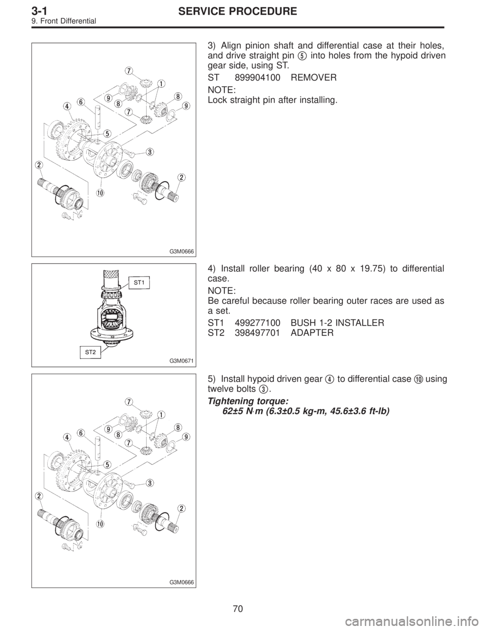
G3M0666
3) Align pinion shaft and differential case at their holes,
and drive straight pin�
5into holes from the hypoid driven
gear side, using ST.
ST 899904100 REMOVER
NOTE:
Lock straight pin after installing.
G3M0671
4) Install roller bearing (40 x 80 x 19.75) to differential
case.
NOTE:
Be careful because roller bearing outer races are used as
a set.
ST1 499277100 BUSH 1-2 INSTALLER
ST2 398497701 ADAPTER
G3M0666
5) Install hypoid driven gear�4to differential case�10using
twelve bolts�
3.
Tightening torque:
62±5 N⋅m (6.3±0.5 kg-m, 45.6±3.6 ft-lb)
70
3-1SERVICE PROCEDURE
9. Front Differential
Page 708 of 3342

1. Automatic Transmission and
Differential
A: SPECIFICATIONS
Torque
converter
clutchType Symmetric, 3 element, single stage, 2 phase torque converter clutch coupling
Stall torque ratio2200 cc 2.1 — 2.3
2500 cc 1.8 — 2.0
OUTBACK 2.2 — 2.4
Nominal diameter2200 cc 236 mm (9.29 in)
2500 cc 246 mm (9.69 in)
Stall speed (at sea level)2200 cc 2,200 — 2,600 rpm
2500 cc 2,200 — 2,600 rpm
OUTBACK 2,300 — 2,700 rpm
One-way clutch Sprague type one-way clutch
Automatic
transmissionTransmissionType 4-forward, 1-reverse, double-row planetary gears
Control elementMulti-plate clutch 4 sets
Multi-plate brake 1 set
Band brake 1 set
One-way clutch (sprague type) 2 sets
Gear ratio1st2200 cc 2.785
2500 cc 3.027
2nd2200 cc 1.545
2500 cc 1.619
3rd 1.000
4th 0.694
Reverse 2.272
Tooth number of
planetary gearFront sun gear 33
Front pinion 21
Front internal gear 75
Rear sun gear2200 cc 42
2500 cc 37
Rear pinion2200 cc 17
2500 cc 19
Rear internal gear 75
Clutch number of reverse
clutchDrive plate & driven plate 2
Clutch number of
high clutchDrive plate & driven plate2200 cc ... 4
2500 cc ... 5
Clutch number of forward
clutchDrive plate & driven plate 5
Clutch number of
overrunning clutchDrive plate & driven plate 3
Clutch number of low &
reverse brakeDrive plate & driven plateExcept OUTBACK ... 5
OUTBACK ... 6
Selector positionP (Park)Transmission in neutral, output member
immovable, and engine start possible
R (Reverse) Transmission in reverse for backing
N (Neutral) Transmission in neutral, and engine start possible
D (Drive) Automatic gear change 1st
+
,2nd+
,3rd+
,4th
3 (3rd) Automatic gear change 1st+
,2nd+
,3rd+4th
2 (2nd)2nd gear locked
(Deceleration possible 4th,3rd,2nd)
1 (1st)1st gear locked
(Deceleration possible 4th,3rd,2nd,1st)
Control method Hydraulic remote control
2
3-2SPECIFICATIONS AND SERVICE DATA
1. Automatic Transmission and Differential
Page 716 of 3342
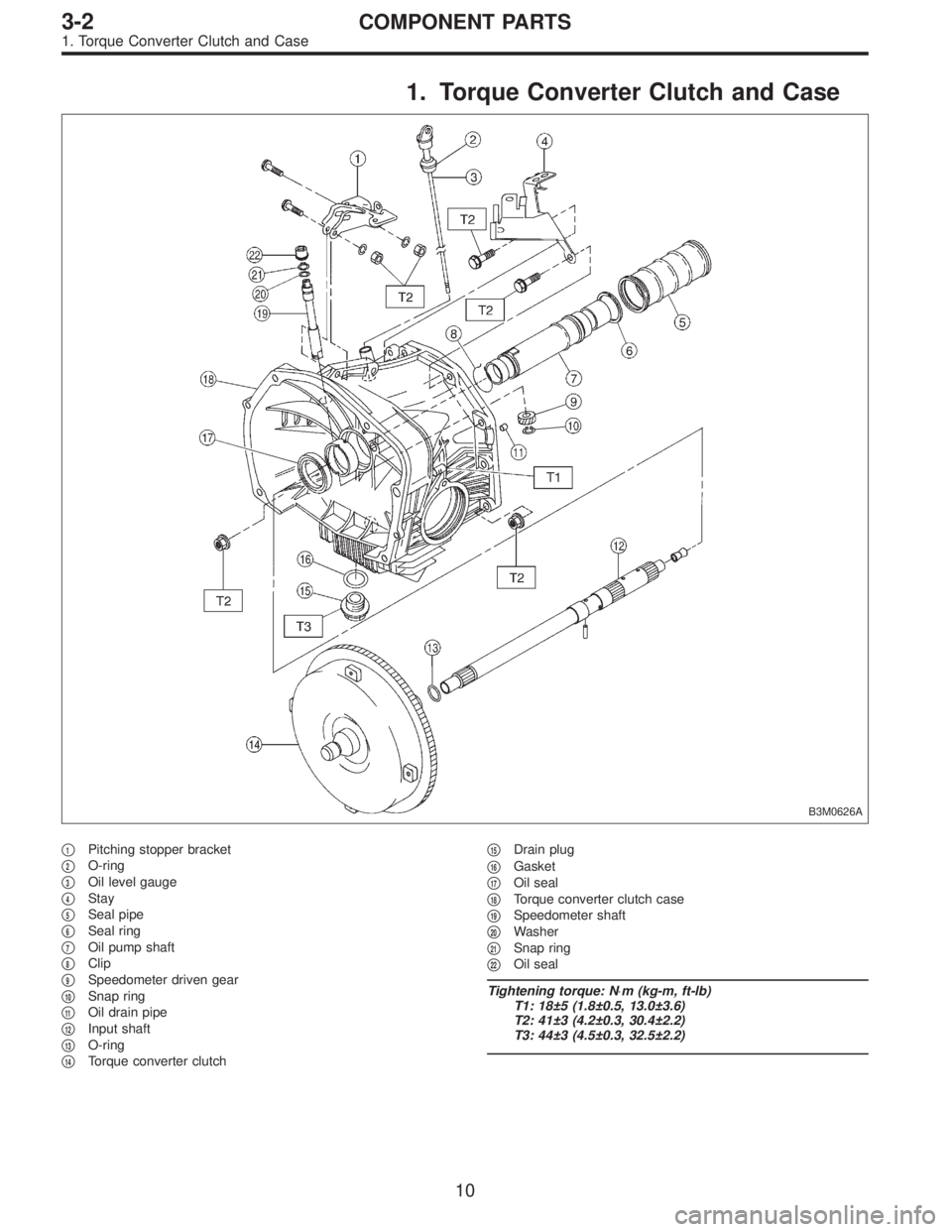
1. Torque Converter Clutch and Case
B3M0626A
�1Pitching stopper bracket
�
2O-ring
�
3Oil level gauge
�
4Stay
�
5Seal pipe
�
6Seal ring
�
7Oil pump shaft
�
8Clip
�
9Speedometer driven gear
�
10Snap ring
�
11Oil drain pipe
�
12Input shaft
�
13O-ring
�
14Torque converter clutch�
15Drain plug
�
16Gasket
�
17Oil seal
�
18Torque converter clutch case
�
19Speedometer shaft
�
20Washer
�
21Snap ring
�
22Oil seal
Tightening torque: N⋅m (kg-m, ft-lb)
T1: 18±5 (1.8±0.5, 13.0±3.6)
T2: 41±3 (4.2±0.3, 30.4±2.2)
T3: 44±3 (4.5±0.3, 32.5±2.2)
10
3-2COMPONENT PARTS
1. Torque Converter Clutch and Case
Page 717 of 3342
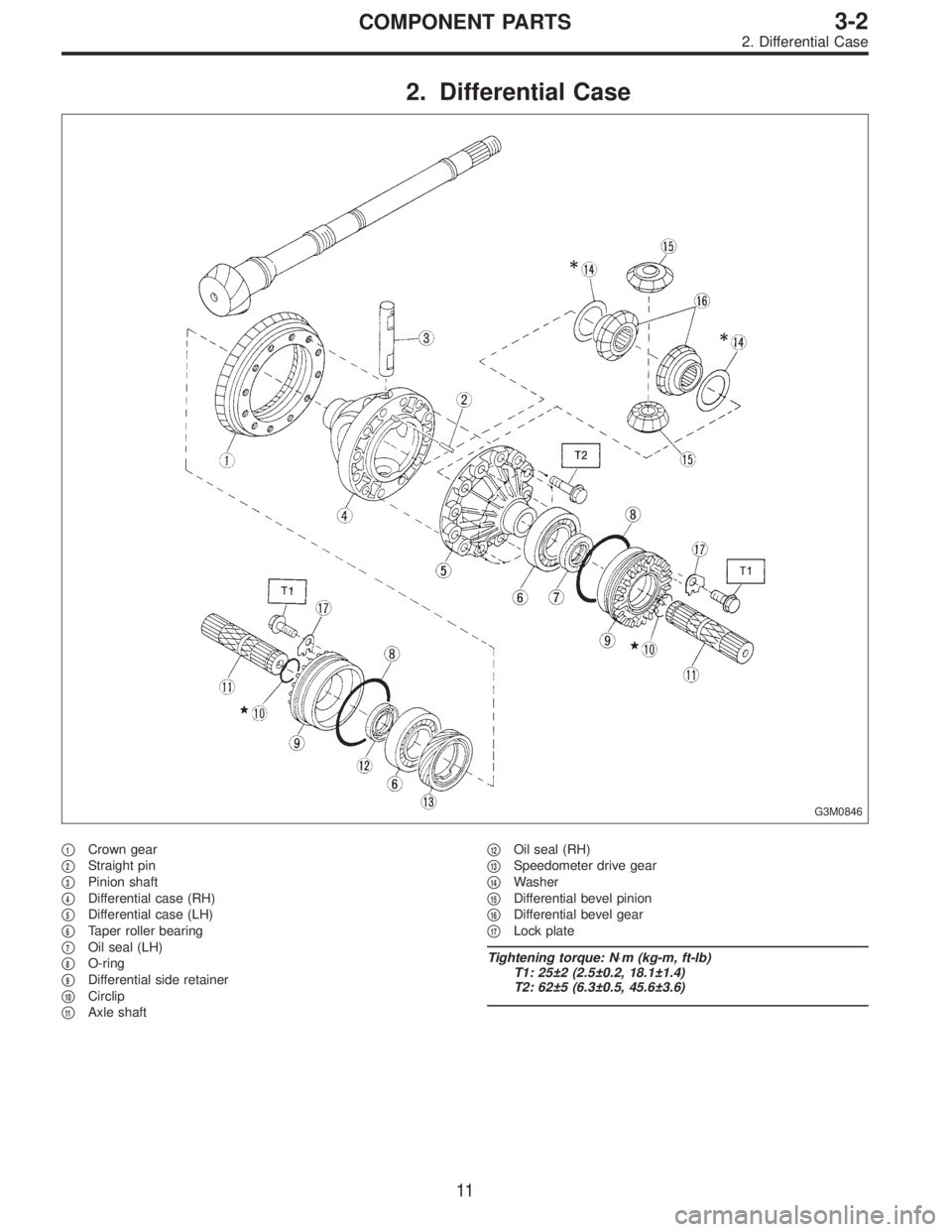
2. Differential Case
G3M0846
�1Crown gear
�
2Straight pin
�
3Pinion shaft
�
4Differential case (RH)
�
5Differential case (LH)
�
6Taper roller bearing
�
7Oil seal (LH)
�
8O-ring
�
9Differential side retainer
�
10Circlip
�
11Axle shaft�
12Oil seal (RH)
�
13Speedometer drive gear
�
14Washer
�
15Differential bevel pinion
�
16Differential bevel gear
�
17Lock plate
Tightening torque: N⋅m (kg-m, ft-lb)
T1: 25±2 (2.5±0.2, 18.1±1.4)
T2: 62±5 (6.3±0.5, 45.6±3.6)
11
3-2COMPONENT PARTS
2. Differential Case
Page 718 of 3342
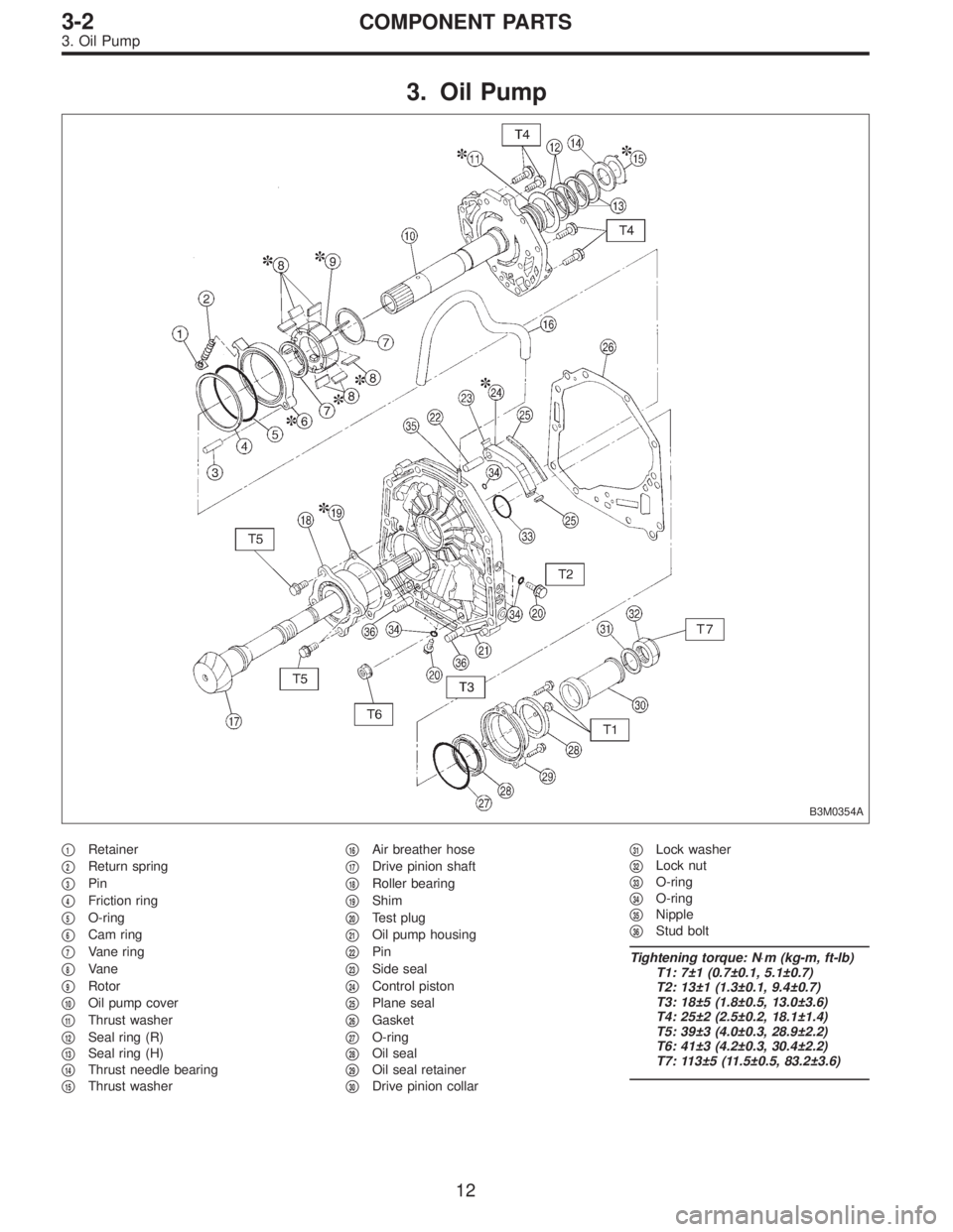
3. Oil Pump
B3M0354A
�1Retainer
�
2Return spring
�
3Pin
�
4Friction ring
�
5O-ring
�
6Cam ring
�
7Vane ring
�
8Vane
�
9Rotor
�
10Oil pump cover
�
11Thrust washer
�
12Seal ring (R)
�
13Seal ring (H)
�
14Thrust needle bearing
�
15Thrust washer�
16Air breather hose
�
17Drive pinion shaft
�
18Roller bearing
�
19Shim
�
20Test plug
�
21Oil pump housing
�
22Pin
�
23Side seal
�
24Control piston
�
25Plane seal
�
26Gasket
�
27O-ring
�
28Oil seal
�
29Oil seal retainer
�
30Drive pinion collar�
31Lock washer
�
32Lock nut
�
33O-ring
�
34O-ring
�
35Nipple
�
36Stud bolt
Tightening torque: N⋅m (kg-m, ft-lb)
T1: 7±1 (0.7±0.1, 5.1±0.7)
T2: 13±1 (1.3±0.1, 9.4±0.7)
T3: 18±5 (1.8±0.5, 13.0±3.6)
T4: 25±2 (2.5±0.2, 18.1±1.4)
T5: 39±3 (4.0±0.3, 28.9±2.2)
T6: 41±3 (4.2±0.3, 30.4±2.2)
T7: 113±5 (11.5±0.5, 83.2±3.6)
12
3-2COMPONENT PARTS
3. Oil Pump
 Install ball bearing (29 x 74 x 38) on drive pinion shaft
with ST.
ST 499277100 INSTALLER
G3M0617
11) Position woodruff key in groove on the rear of drive
pinion shaft. Install 5th driven")