Page 745 of 3342

Be sure to cool down the engine for at least one minute
after each stall test with the select lever set in the P or
N range and with the idle speed lower than 1,200 rpm.
�If the stall speed is higher than the specified range,
attempt to finish the stall test in as short a time as
possible, in order to prevent the automatic transmis-
sion from sustaining damage.
Specifications
Stall speed (at sea level):
2200 cc 2,200 — 2,600 rpm
2500 cc 2,200 — 2,600 rpm
OUTBACK 2,300 — 2,700 rpm
3. EVALUATION
Stall speed
(at sea level)Position Cause
Less than specifications2
R�Throttle valve not fully open
�Erroneous engine operation
�Torque converter clutch’s one-way clutch slipping
Greater than specificationsD�Forward clutch slipping
�One-way clutch (1-2) malfunctioning
R�Line pressure too low
�Reverse clutch slipping
�Low & reverse brake slipping
2�Line pressure too low
�Forward clutch slipping
�Brake band slipping
�One-way clutch (3-4) malfunctioning
39
3-2SERVICE PROCEDURE
3. Performance Test
Page 754 of 3342
G3M0871
A: DISASSEMBLY
1. EXTERNAL PARTS
1) Place the transmission unit on a work bench, with the
oil pan facing down.
CAUTION:
Be careful not to bend or damage external parts.
G3M0325
2) Remove the drain plug, and drain differential oil. Tighten
the plug temporarily after draining.
G3M0326
3) Remove the drain plug, and drain automatic transmis-
sion fluid (ATF). Tighten the plug temporarily after draining.
G3M0327
4) Extract the torque converter clutch assembly.
NOTE:
�Extract the torque converter clutch horizontally. Be care-
ful not to scratch the bushing inside the oil pump shaft.
�Note that oil pump shaft also comes out.
G3M0328
5) Remove the input shaft.
48
3-2SERVICE PROCEDURE
4. Overall Transmission
Page 756 of 3342
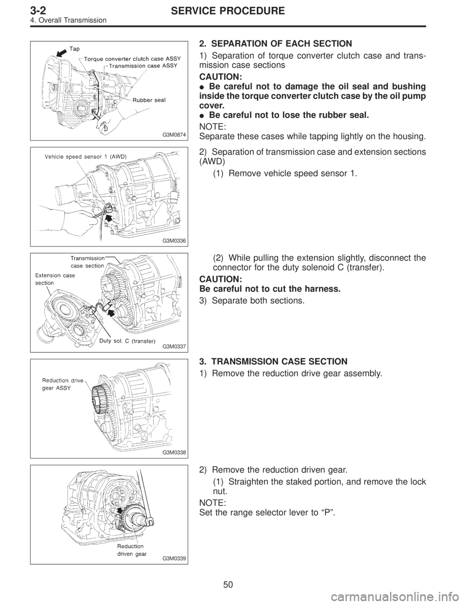
G3M0874
2. SEPARATION OF EACH SECTION
1) Separation of torque converter clutch case and trans-
mission case sections
CAUTION:
�Be careful not to damage the oil seal and bushing
inside the torque converter clutch case by the oil pump
cover.
�Be careful not to lose the rubber seal.
NOTE:
Separate these cases while tapping lightly on the housing.
G3M0336
2) Separation of transmission case and extension sections
(AWD)
(1) Remove vehicle speed sensor 1.
G3M0337
(2) While pulling the extension slightly, disconnect the
connector for the duty solenoid C (transfer).
CAUTION:
Be careful not to cut the harness.
3) Separate both sections.
G3M0338
3. TRANSMISSION CASE SECTION
1) Remove the reduction drive gear assembly.
G3M0339
2) Remove the reduction driven gear.
(1) Straighten the staked portion, and remove the lock
nut.
NOTE:
Set the range selector lever to“P”.
50
3-2SERVICE PROCEDURE
4. Overall Transmission
Page 763 of 3342
G3M0366
30) Remove the inhibitor switch.
G3M0367
31) Remove the transmission harness.
CAUTION:
Be careful not to damage the cord insulation.
G3M0368
4. TORQUE CONVERTER CLUTCH CASE SECTION
1) Wrap the axle shaft serration with vinyl tape.
2) Remove the differential side retainer with ST.
ST 499787000 WRENCH ASSY
CAUTION:
Hold the differential case assembly by hand to avoid
damaging retainer mounting hole of the torque con-
verter clutch case and speedometer gears.
G3M0956
3) Extract the axle shaft with ST1 and ST2.
ST1 499095500 REMOVER
ST2 499247300 INSTALLER
CAUTION:
Do not reuse the circlip.
G3M0370
4) Remove the differential case assembly.
CAUTION:
�Remove the seal pipe if it is attached. (Reusing is
not allowed.)
�Be careful not to damage the retainer mounting hole
of the torque converter clutch case and the speedom-
eter gears.
57
3-2SERVICE PROCEDURE
4. Overall Transmission
Page 765 of 3342
 Check the appearance of each component and clean.
CAUTION:
Make sure each part is free of harmful cuts, damage
and other")
B: ASSEMBLY OF OVERALL TRANSMISSION
1. TORQUE CONVERTER CLUTCH CASE SECTION
1) Check the appearance of each component and clean.
CAUTION:
Make sure each part is free of harmful cuts, damage
and other faults.
G3M0377
2) Install the washer and snap ring to the speedometer
shaft with ST, and set the oil seal. Then force-fit the shaft
to the torque converter clutch case.
ST 499827000 PRESS
3) Install vehicle speed sensor 2.
CAUTION:
Use new vehicle speed sensor 2, if it has been
removed.
Tightening torque:
5.9±1.5 N⋅m (60±15 kg-cm, 52±13 in-lb)
G3M0378
4) Install the speedometer driven gear to the speedometer
shaft, and secure with a snap ring.
G3M0379
5) Force-fit the oil seal to the torque converter clutch case
with ST.
ST 398437700 DRIFT
G3M0380
6) Install the differential assembly to the case, paying spe-
cial attention not to damage the speedometer gears (drive
and driven) and the inside of the case (particularly, the dif-
ferential side retainer contact surface).
59
3-2SERVICE PROCEDURE
4. Overall Transmission
Page 767 of 3342
 Tighten four bolts to secure the roller bearing.
Tightening torque:
39±3 N⋅m (4.0±0.3 kg-m, 28.9±2.2 ft-lb)
G3M0883
(3) Install the oil pump housing assembly to the torque
converter c")
G3M0383
(2) Tighten four bolts to secure the roller bearing.
Tightening torque:
39±3 N⋅m (4.0±0.3 kg-m, 28.9±2.2 ft-lb)
G3M0883
(3) Install the oil pump housing assembly to the torque
converter clutch case, and secure evenly by tightening
four bolts.
Tightening torque:
41±3 N⋅m (4.2±0.3 kg-m, 30.4±2.2 ft-lb)
CAUTION:
�Thoroughly remove the liquid gasket from the case
mating surface beforehand.
�Use an old gasket or an aluminum washer so as not
to damage the mating surface of the housing.
G3M0384
(4) Rotate the drive pinion several times with ST1 and
ST2.
ST1 498937100 HOLDER
ST2 499787100 WRENCH
G3M0884
(5) Tighten the LH retainer until contact is felt while
rotating the shaft. Then loosen the RH retainer. Keep
tightening the LH retainer and loosening the RH
retainer until the pinion shaft can no longer be turned.
This is the“zero”state.
G3M0885
(6) After the“zero”state is established, back off the LH
retainer 3 notches and secure it with the lock plate.
Then back off the RH retainer and retighten until it
stops. Repeat this procedure several times. Tighten the
RH retainer 1-3/4 notches further. This sets the preload.
Finally, secure the retainer with its lock plate.
NOTE:
Turning the retainer by one tooth changes the backlash
about 0.05 mm (0.0020 in).
61
3-2SERVICE PROCEDURE
4. Overall Transmission
Page 770 of 3342
 If tooth contact is correct, mark the retainer position
and loosen it. After fitting the O-ring, screw in the
retainer to the marked position. Then tighten the lock
plate to the specified")
G3M0885
(9) If tooth contact is correct, mark the retainer position
and loosen it. After fitting the O-ring, screw in the
retainer to the marked position. Then tighten the lock
plate to the specified torque.
Tightening torque:
25±2 N⋅m (2.5±0.2 kg-m, 18.1±1.4 ft-lb)
G3M0370
12) Install the seal pipe to the torque converter clutch
case.
CAUTION:
Be sure to use a new seal pipe.
G3M0390
13) Install two oil seals to the oil seal retainer with ST.
ST 499247300 INSTALLER
CAUTION:
�Always discard old oil seals, and install new ones.
�Pay attention to the orientation of the oil seals.
G3M0886
14) Attach the O-ring to the oil seal retainer with vaseline.
Install the seal to the oil pump housing bore.
CAUTION:
Always discard old O-rings and install new ones.
G3M0392
15) Install the oil seal retainer taking care not to damage
the oil seal lips. Then secure with three bolts.
NOTE:
Make sure the O-ring is fitted correctly in position.
Tightening torque:
7±1 N⋅m (0.7±0.1 kg-m, 5.1±0.7 ft-lb)
64
3-2SERVICE PROCEDURE
4. Overall Transmission
Page 771 of 3342
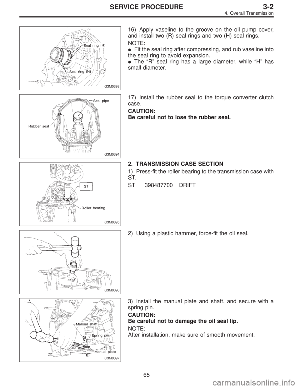
G3M0393
16) Apply vaseline to the groove on the oil pump cover,
and install two (R) seal rings and two (H) seal rings.
NOTE:
�Fit the seal ring after compressing, and rub vaseline into
the seal ring to avoid expansion.
�The“R”seal ring has a large diameter, while“H”has
small diameter.
G3M0394
17) Install the rubber seal to the torque converter clutch
case.
CAUTION:
Be careful not to lose the rubber seal.
G3M0395
2. TRANSMISSION CASE SECTION
1) Press-fit the roller bearing to the transmission case with
ST.
ST 398487700 DRIFT
G3M0396
2) Using a plastic hammer, force-fit the oil seal.
G3M0397
3) Install the manual plate and shaft, and secure with a
spring pin.
CAUTION:
Be careful not to damage the oil seal lip.
NOTE:
After installation, make sure of smooth movement.
65
3-2SERVICE PROCEDURE
4. Overall Transmission
 Place the transmission unit on a work bench, with the
oil pan facing down.
CAUTION:
Be careful not to bend or damage external parts.
G3M0325
2) Remove the d")
 Remove the inhibitor switch.
G3M0367
31) Remove the transmission harness.
CAUTION:
Be careful not to damage the cord insulation.
G3M0368
4. TORQUE CONVERTER CLUTCH CASE SECTION
1) Wrap the")