Page 818 of 3342
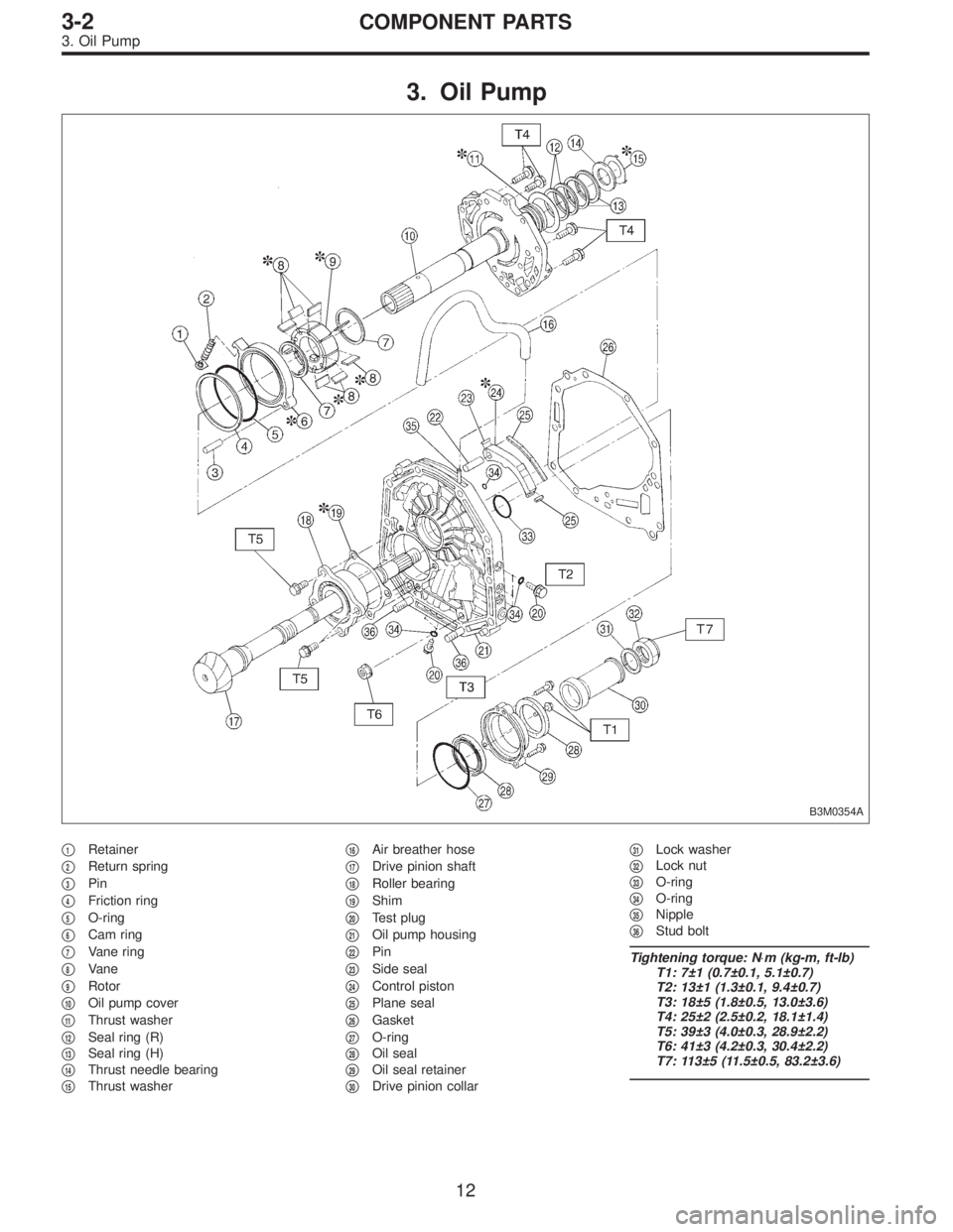
3. Oil Pump
B3M0354A
�1Retainer
�
2Return spring
�
3Pin
�
4Friction ring
�
5O-ring
�
6Cam ring
�
7Vane ring
�
8Vane
�
9Rotor
�
10Oil pump cover
�
11Thrust washer
�
12Seal ring (R)
�
13Seal ring (H)
�
14Thrust needle bearing
�
15Thrust washer�
16Air breather hose
�
17Drive pinion shaft
�
18Roller bearing
�
19Shim
�
20Test plug
�
21Oil pump housing
�
22Pin
�
23Side seal
�
24Control piston
�
25Plane seal
�
26Gasket
�
27O-ring
�
28Oil seal
�
29Oil seal retainer
�
30Drive pinion collar�
31Lock washer
�
32Lock nut
�
33O-ring
�
34O-ring
�
35Nipple
�
36Stud bolt
Tightening torque: N⋅m (kg-m, ft-lb)
T1: 7±1 (0.7±0.1, 5.1±0.7)
T2: 13±1 (1.3±0.1, 9.4±0.7)
T3: 18±5 (1.8±0.5, 13.0±3.6)
T4: 25±2 (2.5±0.2, 18.1±1.4)
T5: 39±3 (4.0±0.3, 28.9±2.2)
T6: 41±3 (4.2±0.3, 30.4±2.2)
T7: 113±5 (11.5±0.5, 83.2±3.6)
12
3-2COMPONENT PARTS
3. Oil Pump
Page 819 of 3342
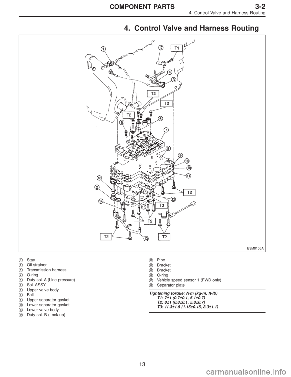
4. Control Valve and Harness Routing
B3M0106A
�1Stay
�
2Oil strainer
�
3Transmission harness
�
4O-ring
�
5Duty sol. A (Line pressure)
�
6Sol. ASSY
�
7Upper valve body
�
8Ball
�
9Upper separator gasket
�
10Lower separator gasket
�
11Lower valve body
�
12Duty sol. B (Lock-up)�
13Pipe
�
14Bracket
�
15Bracket
�
16O-ring
�
17Vehicle speed sensor 1 (FWD only)
�
18Separator plate
Tightening torque: N⋅m (kg-m, ft-lb)
T1: 7±1 (0.7±0.1, 5.1±0.7)
T2: 8±1 (0.8±0.1, 5.8±0.7)
T3: 11.3±1.5 (1.15±0.15, 8.3±1.1)
13
3-2COMPONENT PARTS
4. Control Valve and Harness Routing
Page 821 of 3342

�
6Inhibitor switch ASSY (Plastic body type)
�
7Nipple
�
8Plate ASSY
�
9Air breather hose
�
10Oil level gauge")
�1Plug
�
2Snap ring
�
3Oil seal
�
4Manual shaft
�
5Range select lever (Plastic body type)
�
6Inhibitor switch ASSY (Plastic body type)
�
7Nipple
�
8Plate ASSY
�
9Air breather hose
�
10Oil level gauge
�
11O-ring
�
12Oil charger pipe
�
13Gasket
�
14Relief valve
�
15Pipe
�
16Gasket
�
17Transmission cover (FWD model)
�
18Shim
�
19Roller bearing
�
20Parking support
�
21Ball bearing
�
22Parking rod
�
23Return spring
�
24Shaft
�
25Parking pawl
�
26Gasket
�
27Inlet pipe
�
28Test plug
�
29O-ring
�
30Spring
�
31O-ring
�
32Accumulator piston (N-D)
�
33O-ring
�
34O-ring
�
35Accumulator piston (2-3)
�
36O-ring
�
37Spring
�
38O-ring
�
39Accumulator piston (1-2)
�
40O-ring�
41Spring
�
42O-ring
�
43Accumulator piston (3-4)
�
44O-ring
�
45Spring
�
46Magnet
�
47Oil pan
�
48Gasket
�
49Drain plug
�
50Detention spring
�
51Pipe (AWD model)
�
52Plug (FWD model)
�
53Gasket (FWD model)
�
54Gasket
�
55Outlet pipe
�
56Spring
�
57Ball
�
58Stopper
�
59Manual lever
�
60Manual plate
�
61Spring pin
�
62Stud bolt
�
63Range select lever (Aluminum body type)
�
64Inhibitor switch (Aluminum body type)
�
65Clip (Aluminum body type)
Tightening torque: N⋅m (kg-m, ft-lb)
T1: 3.4±0.5 (0.35±0.05, 2.5±0.4)
T2: 4.9±0.5 (0.50±0.05, 3.6±0.4)
T3: 5.9±1.0 (0.60±0.10, 4.3±0.7)
T4: 6.4±0.5 (0.65±0.05, 4.7±0.4)
T5: 7.8±1.0 (0.80±0.10, 5.8±0.7)
T6: 12.7±1.0 (1.30±0.10, 9.4±0.7)
T7: 17.7±2.9 (1.80±0.30, 13.0±2.2)
T8: 24.5±2.0 (2.50±0.20, 18.1±1.4)
T9: 30.9±3.4 (3.15±0.35, 22.8±2.5)
T10: 34.3±2.9 (3.50±0.30, 25.3±2.2)
T11: 47.1±2.0 (4.80±0.20, 34.7±1.4)
T12: 47.1±4.9 (4.80±0.50, 34.7±3.6)
15
3-2COMPONENT PARTS
5. Transmission Case, Transmission Cover and Control Device
Page 822 of 3342
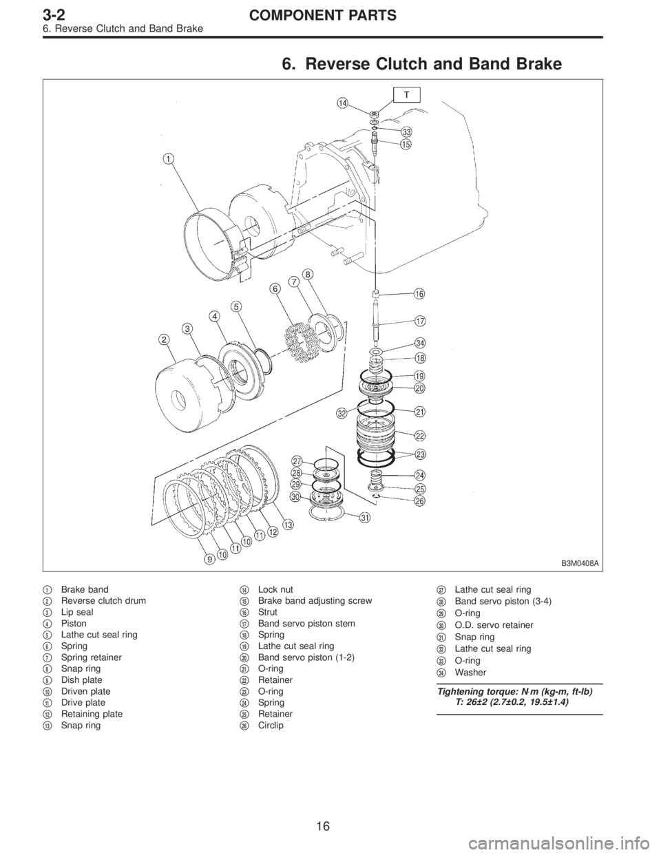
6. Reverse Clutch and Band Brake
B3M0408A
�1Brake band
�
2Reverse clutch drum
�
3Lip seal
�
4Piston
�
5Lathe cut seal ring
�
6Spring
�
7Spring retainer
�
8Snap ring
�
9Dish plate
�
10Driven plate
�
11Drive plate
�
12Retaining plate
�
13Snap ring�
14Lock nut
�
15Brake band adjusting screw
�
16Strut
�
17Band servo piston stem
�
18Spring
�
19Lathe cut seal ring
�
20Band servo piston (1-2)
�
21O-ring
�
22Retainer
�
23O-ring
�
24Spring
�
25Retainer
�
26Circlip�
27Lathe cut seal ring
�
28Band servo piston (3-4)
�
29O-ring
�
30O.D. servo retainer
�
31Snap ring
�
32Lathe cut seal ring
�
33O-ring
�
34Washer
Tightening torque: N⋅m (kg-m, ft-lb)
T: 26±2 (2.7±0.2, 19.5±1.4)
16
3-2COMPONENT PARTS
6. Reverse Clutch and Band Brake
Page 824 of 3342
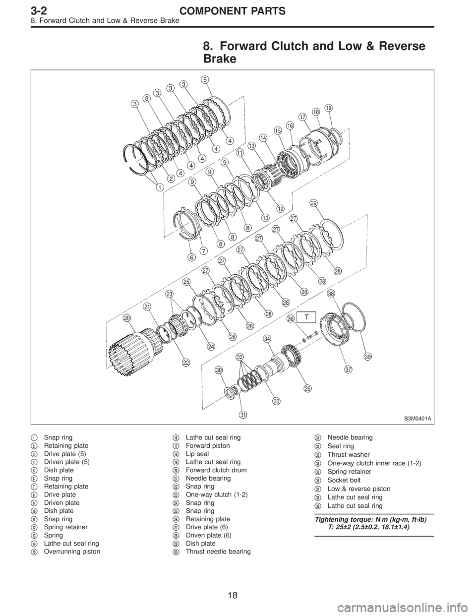
8. Forward Clutch and Low & Reverse
Brake
B3M0401A
�1Snap ring
�
2Retaining plate
�
3Drive plate (5)
�
4Driven plate (5)
�
5Dish plate
�
6Snap ring
�
7Retaining plate
�
8Drive plate
�
9Driven plate
�
10Dish plate
�
11Snap ring
�
12Spring retainer
�
13Spring
�
14Lathe cut seal ring
�
15Overrunning piston�
16Lathe cut seal ring
�
17Forward piston
�
18Lip seal
�
19Lathe cut seal ring
�
20Forward clutch drum
�
21Needle bearing
�
22Snap ring
�
23One-way clutch (1-2)
�
24Snap ring
�
25Snap ring
�
26Retaining plate
�
27Drive plate (6)
�
28Driven plate (6)
�
29Dish plate
�
30Thrust needle bearing�
31Needle bearing
�
32Seal ring
�
33Thrust washer
�
34One-way clutch inner race (1-2)
�
35Spring retainer
�
36Socket bolt
�
37Low & reverse piston
�
38Lathe cut seal ring
�
39Lathe cut seal ring
Tightening torque: N⋅m (kg-m, ft-lb)
T: 25±2 (2.5±0.2, 18.1±1.4)
18
3-2COMPONENT PARTS
8. Forward Clutch and Low & Reverse Brake
Page 825 of 3342
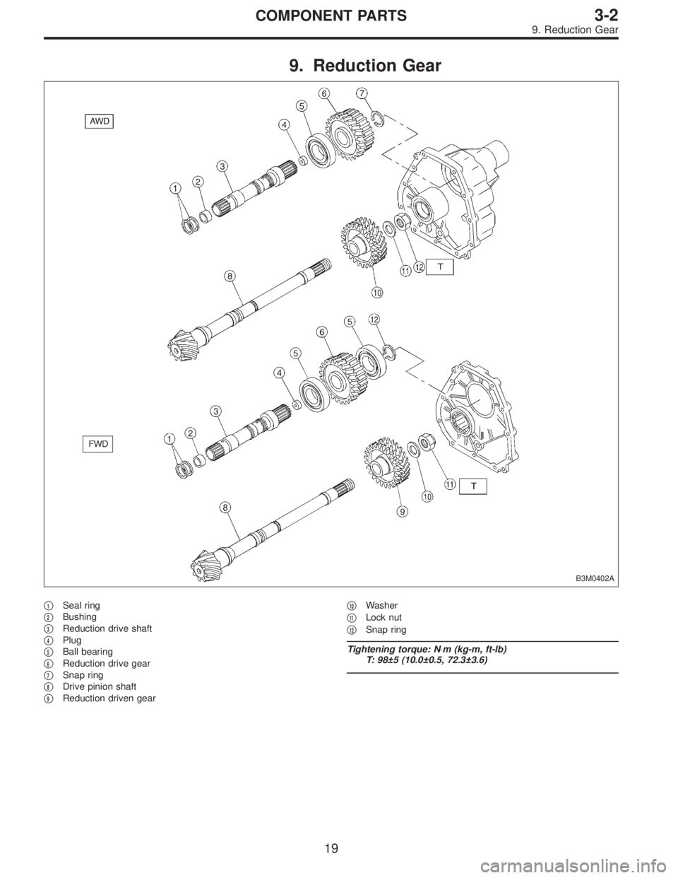
9. Reduction Gear
B3M0402A
�1Seal ring
�
2Bushing
�
3Reduction drive shaft
�
4Plug
�
5Ball bearing
�
6Reduction drive gear
�
7Snap ring
�
8Drive pinion shaft
�
9Reduction driven gear�
10Washer
�
11Lock nut
�
12Snap ring
Tightening torque: N⋅m (kg-m, ft-lb)
T: 98±5 (10.0±0.5, 72.3±3.6)
19
3-2COMPONENT PARTS
9. Reduction Gear
Page 826 of 3342
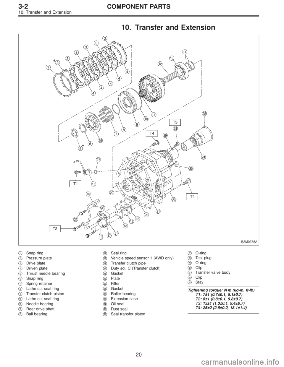
10. Transfer and Extension
B3M0375A
�1Snap ring
�
2Pressure plate
�
3Drive plate
�
4Driven plate
�
5Thrust needle bearing
�
6Snap ring
�
7Spring retainer
�
8Lathe cut seal ring
�
9Transfer clutch piston
�
10Lathe cut seal ring
�
11Needle bearing
�
12Rear drive shaft
�
13Ball bearing�
14Seal ring
�
15Vehicle speed sensor 1 (AWD only)
�
16Transfer clutch pipe
�
17Duty sol. C (Transfer clutch)
�
18Gasket
�
19Plate
�
20Filter
�
21Gasket
�
22Roller bearing
�
23Extension case
�
24Oil seal
�
25Dust seal
�
26Seal transfer piston�
27O-ring
�
28Test plug
�
29O-ring
�
30Clip
�
31Transfer valve body
�
32Clip
�
33Stay
Tightening torque: N⋅m (kg-m, ft-lb)
T1: 7±1 (0.7±0.1, 5.1±0.7)
T2: 8±1 (0.8±0.1, 5.8±0.7)
T3: 13±1 (1.3±0.1, 9.4±0.7)
T4: 25±2 (2.5±0.2, 18.1±1.4)
20
3-2COMPONENT PARTS
10. Transfer and Extension
Page 828 of 3342
G3M0854
(7) Apply the automatic transmission fluid (ATF) onto
the parts immediately prior to assembly, and the speci-
fied tightening torque should be observed carefully.
(8) Use vaseline if it is necessary to hold parts in the
position when assembling.
(9) Drain ATF and differential gear oil into a saucer so
that the conditions of fluid and oil can be inspected.
(10) Do not support axle drive shaft, stator shaft, input
shaft or various pipes when moving transmission from
one place to another.
(11) Always discard old oil seals and O-ring, and install
new ones.
(12) Do not reuse old aluminum (overrunning clutch
pipes, etc.) pipes, gaskets, spring pins. Install new
ones.
(13) Be sure to replace parts which are damaged,
worn, scratched, discolored, etc.
22
3-2SERVICE PROCEDURE
1. Precaution
 Apply the automatic transmission fluid (ATF) onto
the parts immediately prior to assembly, and the speci-
fied tightening torque should be observed carefully.
(8) Use vaseline if it is nec")