Page 653 of 3342
B3M0043A
4) Remove reverse check sleeve�5.
Disassembly procedure is as follows:
(1) Using a standard screwdriver, remove snap ring�
A
(Inner-28).
NOTE:
Replace snap ring with a new one if deformed or weak-
ened.
(2) Remove reverse check plate�
B.
(3) Remove reverse check spring�
Cwith cam�D.
(4) Remove reverse return spring�
E.
(5) Remove reverse accent shaft�
F.
(6) Remove O-ring�
G.
NOTE:
�Reverse check sleeve assembly uses an O-ring which
should not be scratched.
�Be careful not to break adjustment shim placed between
reverse check sleeve assembly and case.
B3M0042A
5) Remove back-up light switch�7.
6) Remove oil guide�
9.
Tightening torque:
T1: 6.4±0.5 N⋅m (0.65±0.05 kg-m, 4.7±0.4 ft-lb)
T2: 10±1 N⋅m (1.0±0.1 kg-m, 7.2±0.7 ft-lb)
T3: 19.6±1.5 N⋅m (2.00±0.15 kg-m, 14.5±1.1 ft-lb)
T4: 25±2 N⋅m (2.5±0.2 kg-m, 18.1±1.4 ft-lb)
21
3-1SERVICE PROCEDURE
2. Transfer Case and Extension (AWD Model)
Page 655 of 3342
C: ASSEMBLY
1. EXTENSION
G3M0953
Tightening torque: N⋅m (kg-m, ft-lb)
T: 25±2 (2.5±0.2, 18.1±1.4)
1) Installation of ball bearing�1and selection of snap ring
�
2(Inner-72)
(1) Attach ball bearing�
1(30 x 72 x 17) to extension
and install snap ring�
2.
B3M0044A
(2) Measure clearance between snap ring�2and outer
race of ball bearing�
1with a thickness gauge.
CAUTION:
Replace ball bearing with a new one.
Clearance:
0—0.15 mm (0—0.0059 in)
(3) If the measurement is not within the specification,
select suitable snap ring�
2.
Snap ring (Inner-72)
Part No. Thickness mm (in)
805172071 1.78 (0.0701)
805172072 1.90 (0.0748)
805172073 2.02 (0.0795)
23
3-1SERVICE PROCEDURE
2. Transfer Case and Extension (AWD Model)
Page 658 of 3342
 Installation of shifter arm�1and selector arm�8
Install shifter arm into the partition from the front while
inserting selector arm into the opening in reverse check
sleeve. Pass shaft thro")
B3M0042A
2) Installation of shifter arm�1and selector arm�8
Install shifter arm into the partition from the front while
inserting selector arm into the opening in reverse check
sleeve. Pass shaft through hole in selector arm until its end
comes out of the rear of transfer case.
NOTE:
Apply a coat of gear oil to shifter arm. Also make sure oil
seal is positioned properly.
Tightening torque:
T1: 6.4±0.5 N⋅m (0.65±0.05 kg-m, 4.7±0.4 ft-lb)
T2: 10±1 N⋅m (1.0±0.1 kg-m, 7.2±0.7 ft-lb)
T3: 19.6±1.5 N⋅m (2.00±0.15 kg-m, 14.5±1.1 ft-lb)
T4: 25±2 N⋅m (2.5±0.2 kg-m, 18.1±1.4 ft-lb)
B3M0049A
3. COMBINATION OF TRANSFER CASE AND
EXTENSION ASSEMBLY
1) Install center differential�
1and transfer driven gear�2
into transfer case.
Tightening torque:
T: 37±3 N⋅m (3.8±0.3 kg-m, 27.5±2.2 ft-lb)
B3M0050A
2) Selection of thrust washer (52 x 61 x t)
(1) Measure height“W”between transfer case and ball
bearing on the transfer driven gear�
3.
26
3-1SERVICE PROCEDURE
2. Transfer Case and Extension (AWD Model)
Page 660 of 3342

T1: 15.7±1.5 (1.6±0.15, 11.6±1.1)
T2: 19.6±1.5 (2.00±0.15, 14.5±1.1)
T3: 24.5±2.0 (2.50±0.20, 18.1±1.4)
1) Install transfer cas")
D: INSTALLATION
B3M0053A
Tightening torque: N⋅m (kg-m, ft-lb)
T1: 15.7±1.5 (1.6±0.15, 11.6±1.1)
T2: 19.6±1.5 (2.00±0.15, 14.5±1.1)
T3: 24.5±2.0 (2.50±0.20, 18.1±1.4)
1) Install transfer case�2with extension assembly�1.
2) Secure selector arm to shifter arm with shifter fork
screw�
3. Shifter arm should be caught by pawl of rod.
Selector arm must be engaged with reverse check sleeve
assembly.
3) Adjustment of neutral position
(1) Shift gear into 3rd gear position.
(2) Shifter arm turns lightly toward the 1st/2nd gear
side but heavily toward the reverse gear side because
of the function of the return spring, until arm contacts
the stopper.
(3) Make adjustment so that the heavy stroke (reverse
side) is a little more than the light stroke (1st/2nd side).
(4) To adjust, remove bolts holding reverse check
sleeve assembly�
4to the case, move sleeve assem-
bly outward, and place adjustment shim (0 to 1 ea.)
between sleeve assembly and case to adjust the clear-
ance.
28
3-1SERVICE PROCEDURE
2. Transfer Case and Extension (AWD Model)
Page 662 of 3342
3. Rear Case (FWD Model)
A: DISASSEMBLY
G3M0952
Tightening torque: N⋅m (kg-m, ft-lb)
T1: 6.4±0.5 (0.65±0.05, 4.7±0.4)
T2: 10±1 (1.0±0.1, 7.2±0.7)
T3: 25±2 (2.5±0.2, 18.1±1.4)
1) Remove rear case�1.
2) Remove plug�
2, spring�3and reverse check ball�4.
3) Remove neutral switch�
5.
4) Pull out shifter arm�
6.
5) Remove reverse check sleeve�
7.
NOTE:
The disassembly procedure is the same as for AWD model.
B3M0056A
6) Remove back-up light switch�8.
7) Remove oil seal�
9.
CAUTION:
Do not reuse oil seal.
30
3-1SERVICE PROCEDURE
3. Rear Case (FWD Model)
Page 663 of 3342
 Assembly of rear case is in the reverse order of disas-
sembly.
G3M0952
Tightening torque: N⋅m (kg-m, ft-lb)
T1: 6.4±0.5 (0.65±0.05, 4.7±0.4)
T2: 10±1 (1.0±0.1, 7.2±0.7)
T3: 25�")
B: ASSEMBLY
1) Assembly of rear case is in the reverse order of disas-
sembly.
G3M0952
Tightening torque: N⋅m (kg-m, ft-lb)
T1: 6.4±0.5 (0.65±0.05, 4.7±0.4)
T2: 10±1 (1.0±0.1, 7.2±0.7)
T3: 25±5 (2.5±0.5, 18.1±3.6)
2) Installation of shifter arm�6
Install shifter arm into the partition from the front while
inserting selector arm into the opening in reverse check
sleeve. Pass shaft through hole in selector arm until its end
comes out of the rear of transmission case assembly.
CAUTION:
Apply a coat of gear oil to shifter arm. Also make sure
oil seal is positioned properly.
3) Adjustment of neutral position
NOTE:
After assembling and installing rear case, adjust neutral
position.
(1) Shift gear into 3rd gear position.
(2) Shifter arm turns lightly toward the 1st/2nd gear
side but heavily toward the reverse gear side because
of the function of the return spring, until arm contacts
the stopper.
(3) Make adjustment so that the heavy stroke (reverse
side) is a little more than the light stroke (1st/2nd side).
(4) To adjust, remove bolts holding reverse check
sleeve assembly to the case, move sleeve assembly
outward, and place adjustment shim (0 to 1 ea.)
between sleeve assembly and case to adjust the clear-
ance.
31
3-1SERVICE PROCEDURE
3. Rear Case (FWD Model)
Page 669 of 3342
B: ASSEMBLY
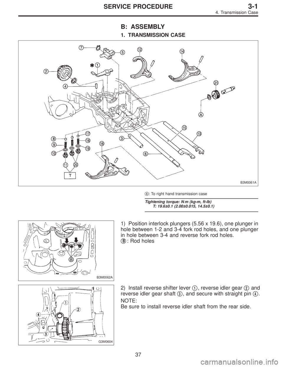
1. TRANSMISSION CASE
B3M0061A
�A: To right hand transmission case
Tightening torque: N⋅m (kg-m, ft-lb)
T: 19.6±0.1 (2.00±0.015, 14.5±0.1)
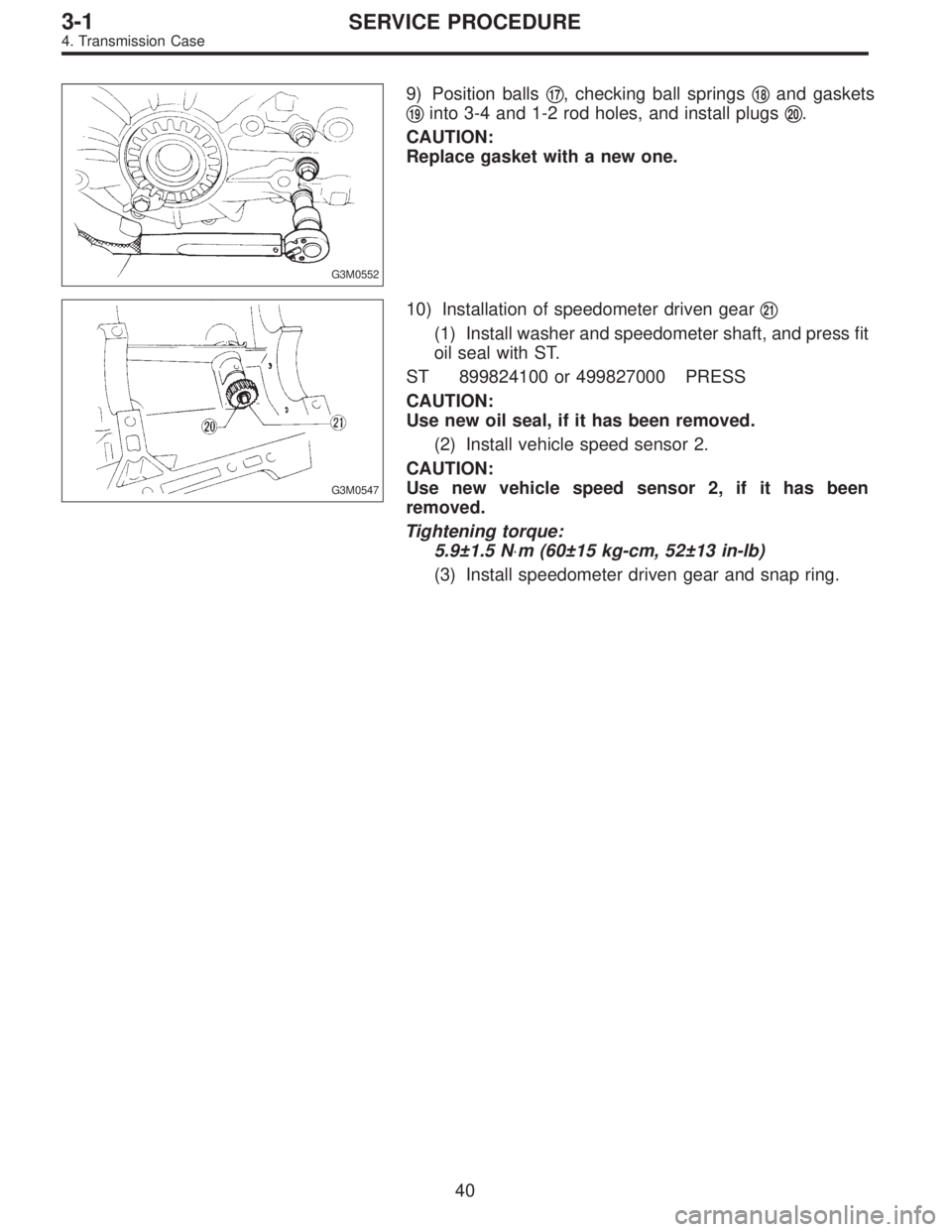
B3M0062A
1) Position interlock plungers (5.56 x 19.6), one plunger in
hole between 1-2 and 3-4 fork rod holes, and one plunger
in hole between 3-4 and reverse fork rod holes.
�
B: Rod holes
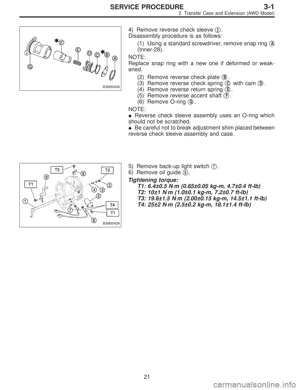
G3M0604
2) Install reverse shifter lever�1, reverse idler gear�2and
reverse idler gear shaft�
3, and secure with straight pin�4.
NOTE:
Be sure to install reverse idler shaft from the rear side.
37
3-1SERVICE PROCEDURE
4. Transmission Case
Page 672 of 3342
G3M0552
9) Position balls�17, checking ball springs�18and gaskets
�
19into 3-4 and 1-2 rod holes, and install plugs�20.
CAUTION:
Replace gasket with a new one.
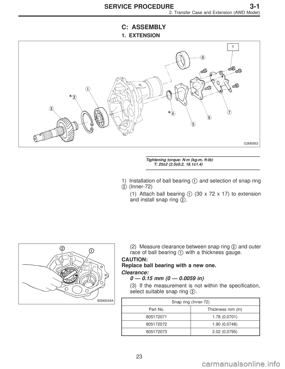
G3M0547
10) Installation of speedometer driven gear�21
(1) Install washer and speedometer shaft, and press fit
oil seal with ST.
ST 899824100 or 499827000 PRESS
CAUTION:
Use new oil seal, if it has been removed.
(2) Install vehicle speed sensor 2.
CAUTION:
Use new vehicle speed sensor 2, if it has been
removed.
Tightening torque:
5.9±1.5 N⋅m (60±15 kg-cm, 52±13 in-lb)
(3) Install speedometer driven gear and snap ring.
40
3-1SERVICE PROCEDURE
4. Transmission Case

A: DISASSEMBLY
G3M0952
Tightening torque: N⋅m (kg-m, ft-lb)
T1: 6.4±0.5 (0.65±0.05, 4.7±0.4)
T2: 10±1 (1.0±0.1, 7.2±0.7)
T3: 25±2 (2.5±0.2, 18.1±1.4)
1) Remove rear")