Page 1728 of 3342
B6M0555A
3) Remove #2 spark plug cord by pulling boot, not cord
itself.
4) For subsequent procedures, refer to the procedure for
#1 spark plug.
CAUTION:
When removing spark plug, cover the ATF cooling
pipes with a rag to prevent damage.
G6M0095
3. #3 SPARK PLUG
1) Disconnect battery ground cable.
B6M0557A
2) Disconnect mass air flow sensor connector.
3) Remove four clips securing air cleaner upper cover.
B6M0558
4) Loosen the clamp screw and separate air cleaner upper
cover from air intake duct.
B6M0565A
5) Remove air cleaner element and air cleaner case.
32
6-1SERVICE PROCEDURE
3. Spark Plug
Page 1729 of 3342
B6M0570A
6) Remove #3 spark plug cord by pulling boot, not cord
itself.
7) For subsequent procedures, refer to the procedure for
#1 spark plug.
G6M0095
4. #4 SPARK PLUG
1) Disconnect battery ground cable.
B6M0554
2) Remove battery.
B6M0561
3) Remove washer tank mounting bolts.
B6M0562A
4) Disconnect washer tank connectors.
CAUTION:
Do not disconnect washer tank hoses as washer fluid
will leak out from washer tank.
33
6-1SERVICE PROCEDURE
3. Spark Plug
Page 1730 of 3342
![SUBARU LEGACY 1997 Service Repair Manual B6M0575A
5) Move washer tank upward.
B6M0563A
6) Remove #4 spark plug cord by pulling boot, not cord
itself.
7) For subsequent procedures, refer to the procedure for
#1 spark plug. <Ref. to 6-1 [W3E1] SUBARU LEGACY 1997 Service Repair Manual B6M0575A
5) Move washer tank upward.
B6M0563A
6) Remove #4 spark plug cord by pulling boot, not cord
itself.
7) For subsequent procedures, refer to the procedure for
#1 spark plug. <Ref. to 6-1 [W3E1]](/manual-img/17/57434/w960_57434-1729.png)
B6M0575A
5) Move washer tank upward.
B6M0563A
6) Remove #4 spark plug cord by pulling boot, not cord
itself.
7) For subsequent procedures, refer to the procedure for
#1 spark plug.
CAUTION:
When removing spark plug, cover the ATF cooling
pipes with a rag to prevent damage.
B6M0572A
NOTE:
For easier removal of spark plug, diagonally insert the tools
from the direction of battery stand into plug hole as shown
in figure.
B6M0573
F: INSTALLATION (2500 cc OUTBACK
MODEL)
1. #1 SPARK PLUG
1) After setting spark plug in spark plug socket, connect
the spark plug socket, extension and Universal Joint to
each other.
2) Screw spark plug into cylinder head using the con-
nected tools above mentioned. At this point, it is necessary
to support the rear end of the tools with fingertips.
3) When spark plug is screwed in two or three turns, tem-
porarily disconnect the tools connected in step 1) above.
4) Confirm that spark plug is screwed into the cylinder
head properly by touching it with finger. If it is difficult to
reach it by hand, confirm its condition by using mirror and
suchlike.
5) Cover ABS pipes with rag to prevent damage.
34
6-1SERVICE PROCEDURE
3. Spark Plug
Page 1732 of 3342

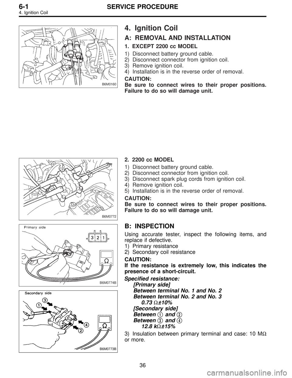
B6M0160
4. Ignition Coil
A: REMOVAL AND INSTALLATION
1. EXCEPT 2200 cc MODEL
1) Disconnect battery ground cable.
2) Disconnect connector from ignition coil.
3) Remove ignition coil.
4) Installation is in the reverse order of removal.
CAUTION:
Be sure to connect wires to their proper positions.
Failure to do so will damage unit.
B6M0772
2. 2200 cc MODEL
1) Disconnect battery ground cable.
2) Disconnect connector from ignition coil.
3) Disconnect spark plug cords from ignition coil.
4) Remove ignition coil.
5) Installation is in the reverse order of removal.
CAUTION:
Be sure to connect wires to their proper positions.
Failure to do so will damage unit.
B6M0774B
B6M0773B
B: INSPECTION
Using accurate tester, inspect the following items, and
replace if defective.
1) Primary resistance
2) Secondary coil resistance
CAUTION:
If the resistance is extremely low, this indicates the
presence of a short-circuit.
Specified resistance:
[Primary side]
Between terminal No. 1 and No. 2
Between terminal No. 2 and No. 3
0.73Ω±10%
[Secondary side]
Between�
1and�2
Between�3and�4
12.8 kΩ±15%
3) Insulation between primary terminal and case: 10 MΩ
or more.
36
6-1SERVICE PROCEDURE
4. Ignition Coil
Page 1733 of 3342
B6M0775
5. Spark Plug Cord
A: INSPECTION
Check for:
1) Damage to cords, deformation, burning or rust forma-
tion of terminals
2) Resistance values of cords
Resistance value:
5.12—12.34 kΩ
G6M0095
6. Ignitor
A: REMOVAL AND INSTALLATION
1) Disconnect battery ground cable.
B6M0161
2) Disconnect connector from ignitor.
3) Remove screws which hold ignitor onto body.
4) Installation is in the reverse order of removal.
37
6-1SERVICE PROCEDURE
5. Spark Plug Cord - 6. Ignitor
Page 1734 of 3342
B6M0775
5. Spark Plug Cord
A: INSPECTION
Check for:
1) Damage to cords, deformation, burning or rust forma-
tion of terminals
2) Resistance values of cords
Resistance value:
5.12—12.34 kΩ
G6M0095
6. Ignitor
A: REMOVAL AND INSTALLATION
1) Disconnect battery ground cable.
B6M0161
2) Disconnect connector from ignitor.
3) Remove screws which hold ignitor onto body.
4) Installation is in the reverse order of removal.
37
6-1SERVICE PROCEDURE
5. Spark Plug Cord - 6. Ignitor
Page 1736 of 3342
2. Generator
Turn ignition switch ON
(engine OFF).
Check if charge bulb
comes on.
YES
�NO
Disconnect generator
body harness
connector.
Turn ignition switch to
“START.”(engine starts.)Check if charge bulb
comes on when terminal
(L) of body harness
connector is grounded.
YES
�NO
Replace charge bulb.
Check IC regulator.
Check positive terminal
of diode.
Check if charge bulb is
OFF while engine idles.
NO
�YES (Remains ON or blinks.)
Check or replace fan belt.
Check generator.
Check S or BAT terminal for improper
contact.
Measure VB* of battery
while running engine at
1,500 rpm.�15.5 V is less than VB.
Replace IC regulator
assembly.
VB is less
than 12.5 V.12.5 V is less than or equal to VB, and
VB is less than or equal to 15.5 V.
Check IC regulator as a
single unit.
Turn light switch ON
while engine idles.�Check if charge bulb
comes on.
YES
�NO
No problems
Check diode assembly.
*: Terminal voltage
�
��
�
�
�
��
�
39
6-1DIAGNOSTICS
2. Generator
Page 1737 of 3342

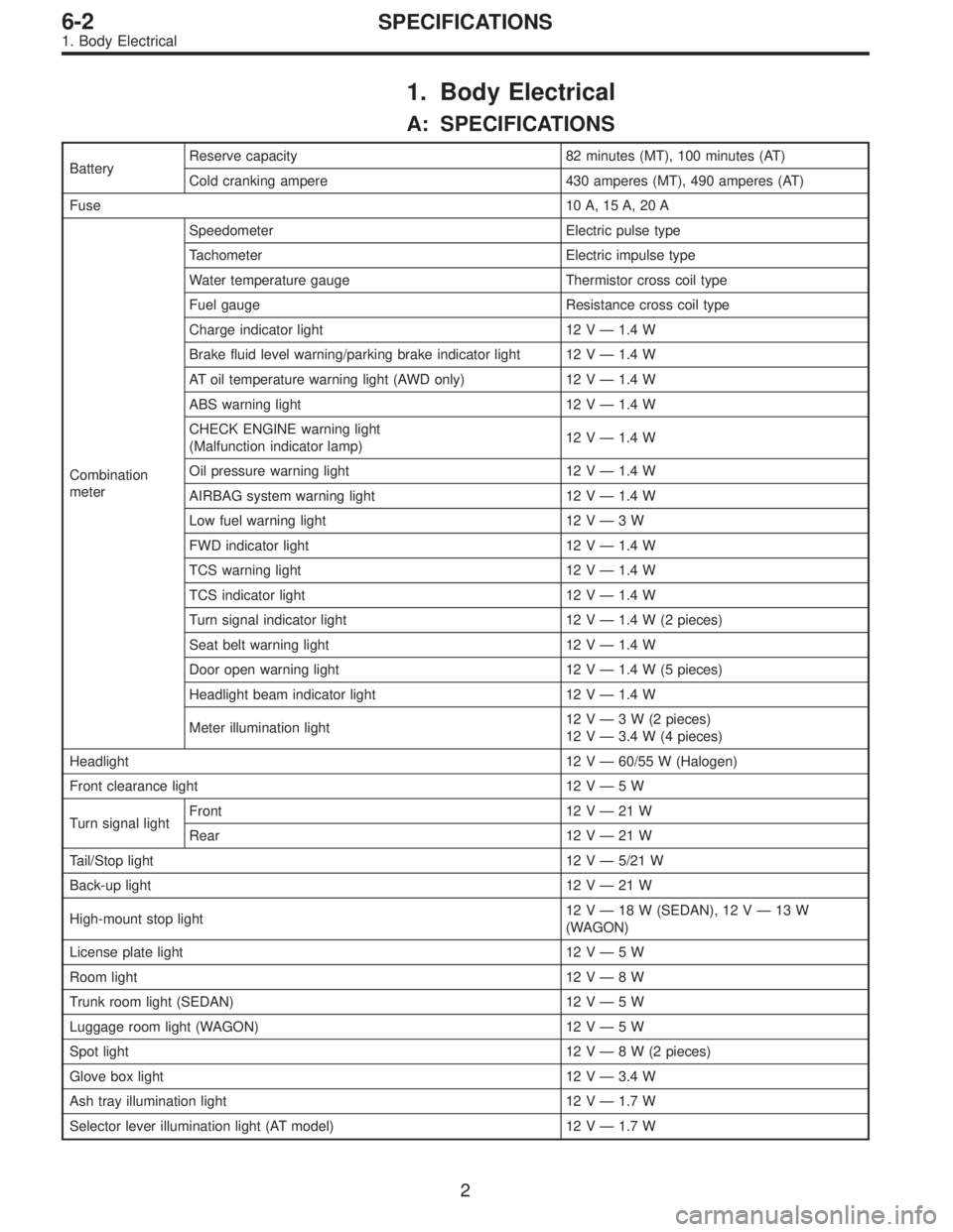
1. Body Electrical
A: SPECIFICATIONS
BatteryReserve capacity 82 minutes (MT), 100 minutes (AT)
Cold cranking ampere 430 amperes (MT), 490 amperes (AT)
Fuse10 A, 15 A, 20 A
Combination
meterSpeedometer Electric pulse type
Tachometer Electric impulse type
Water temperature gauge Thermistor cross coil type
Fuel gauge Resistance cross coil type
Charge indicator light 12 V—1.4 W
Brake fluid level warning/parking brake indicator light 12 V—1.4 W
AT oil temperature warning light (AWD only) 12 V—1.4 W
ABS warning light 12 V—1.4 W
CHECK ENGINE warning light
(Malfunction indicator lamp)12 V—1.4 W
Oil pressure warning light 12 V—1.4 W
AIRBAG system warning light 12 V—1.4 W
Low fuel warning light 12 V—3W
FWD indicator light 12 V—1.4 W
TCS warning light 12 V—1.4 W
TCS indicator light 12 V—1.4 W
Turn signal indicator light 12 V—1.4 W (2 pieces)
Seat belt warning light 12 V—1.4 W
Door open warning light 12 V—1.4 W (5 pieces)
Headlight beam indicator light 12 V—1.4 W
Meter illumination light12 V—3 W (2 pieces)
12 V—3.4 W (4 pieces)
Headlight 12 V—60/55 W (Halogen)
Front clearance light 12 V—5W
Turn signal lightFront 12 V—21 W
Rear 12 V—21 W
Tail/Stop light 12 V—5/21 W
Back-up light 12 V—21 W
High-mount stop light12 V—18 W (SEDAN), 12 V—13 W
(WAGON)
License plate light 12 V—5W
Room light 12 V—8W
Trunk room light (SEDAN) 12 V—5W
Luggage room light (WAGON) 12 V—5W
Spot light 12 V—8 W (2 pieces)
Glove box light 12 V—3.4 W
Ash tray illumination light 12 V—1.7 W
Selector lever illumination light (AT model) 12 V—1.7 W
2
6-2SPECIFICATIONS
1. Body Electrical