Page 1687 of 3342
A: REMOVAL
1. DRIVER SIDE
1) Set front wheels in straight ahead position.
2) Turn ignition switch off.
3) Disconnect ground cable from battery and wait for at
least 20 seconds before starting work.
H5M0662A
4) Using TORX®BIT T30, remove two TORX®bolts.
H5M0664
5) Disconnect airbag connector on back of airbag module.
6) Refer to“CAUTION”for handling of a removed airbag
module.
2. PASSENGER SIDE
1) Remove instrument panel.
12
5-5bSERVICE PROCEDURE
3. Airbag Module
Page 1688 of 3342
B5M0098
2) Remove four bolts and then carefully remove airbag
module.
3) Refer to“CAUTION”for handling of a removed airbag
module.
B: INSTALLATION
Installation is in reverse order of removal procedures.
Observe the following: Make sure that ignition switch is off.
CAUTION:
Do not allow harness and connectors to interfere or
get caught with other parts.
4. Main Harness
A: REMOVAL
1) Turn ignition switch off.
2) Disconnect ground cable from battery and wait for at
least 20 seconds before starting work.
G5M0312
3) Remove lower cover.
Disconnect airbag connector (AB3) and (AB8) below steer-
ing column.
CAUTION:
Do not reconnect airbag connector at steering column
until main harness are securely re-installed.
G5M0313
4) Remove console box. Discon-
nect 12-pin yellow connector (AB6) from airbag control
module.
13
5-5bSERVICE PROCEDURE
3. Airbag Module - 4. Main Harness
Page 1689 of 3342
B5M0098
2) Remove four bolts and then carefully remove airbag
module.
3) Refer to“CAUTION”for handling of a removed airbag
module.
B: INSTALLATION
Installation is in reverse order of removal procedures.
Observe the following: Make sure that ignition switch is off.
CAUTION:
Do not allow harness and connectors to interfere or
get caught with other parts.
4. Main Harness
A: REMOVAL
1) Turn ignition switch off.
2) Disconnect ground cable from battery and wait for at
least 20 seconds before starting work.
G5M0312
3) Remove lower cover.
Disconnect airbag connector (AB3) and (AB8) below steer-
ing column.
CAUTION:
Do not reconnect airbag connector at steering column
until main harness are securely re-installed.
G5M0313
4) Remove console box. Discon-
nect 12-pin yellow connector (AB6) from airbag control
module.
13
5-5bSERVICE PROCEDURE
3. Airbag Module - 4. Main Harness
Page 1692 of 3342
G5M0323
�If the airbag control module is deformed, or if water
damage is suspected, replace the airbag control mod-
ule with a new genuine part.
G5M0324
�After removal, keep the airbag control module on a
dry, clean surface away from heat and light sources,
and moisture and dust.
A: REMOVAL
1) Turn ignition switch off.
2) Disconnect ground cable from battery and wait for at
least 20 seconds before starting work.
G5M0312
3) Remove lower cover.
Disconnect airbag connector (AB3) and (AB8) below steer-
ing column.
CAUTION:
Do not reconnect airbag connector at steering column
until airbag control module is securely re-installed.
B5M0400A
4) Remove console box.
5) Disconnect 12-pin yellow connector from airbag control
module.
15
5-5bSERVICE PROCEDURE
5. Airbag Control Module
Page 1693 of 3342

B5M0105
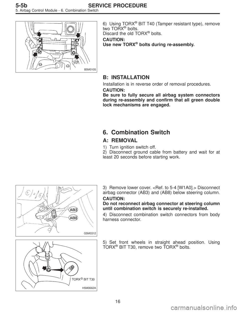
6) Using TORX®BIT T40 (Tamper resistant type), remove
two TORX®bolts.
Discard the old TORX®bolts.
CAUTION:
Use new TORX
®bolts during re-assembly.
B: INSTALLATION
Installation is in reverse order of removal procedures.
CAUTION:
Be sure to fully secure all airbag system connectors
during re-assembly and confirm that all green double
lock mechanisms are engaged.
6. Combination Switch
A: REMOVAL
1) Turn ignition switch off.
2) Disconnect ground cable from battery and wait for at
least 20 seconds before starting work.
G5M0312
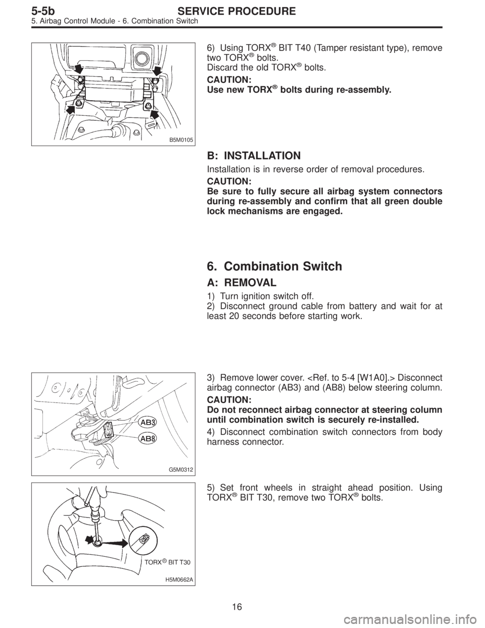
3) Remove lower cover. Disconnect
airbag connector (AB3) and (AB8) below steering column.
CAUTION:
Do not reconnect airbag connector at steering column
until combination switch is securely re-installed.
4) Disconnect combination switch connectors from body
harness connector.
H5M0662A
5) Set front wheels in straight ahead position. Using
TORX®BIT T30, remove two TORX®bolts.
16
5-5bSERVICE PROCEDURE
5. Airbag Control Module - 6. Combination Switch
Page 1694 of 3342

B5M0105
6) Using TORX®BIT T40 (Tamper resistant type), remove
two TORX®bolts.
Discard the old TORX®bolts.
CAUTION:
Use new TORX
®bolts during re-assembly.
B: INSTALLATION
Installation is in reverse order of removal procedures.
CAUTION:
Be sure to fully secure all airbag system connectors
during re-assembly and confirm that all green double
lock mechanisms are engaged.
6. Combination Switch
A: REMOVAL
1) Turn ignition switch off.
2) Disconnect ground cable from battery and wait for at
least 20 seconds before starting work.
G5M0312
3) Remove lower cover. Disconnect
airbag connector (AB3) and (AB8) below steering column.
CAUTION:
Do not reconnect airbag connector at steering column
until combination switch is securely re-installed.
4) Disconnect combination switch connectors from body
harness connector.
H5M0662A
5) Set front wheels in straight ahead position. Using
TORX®BIT T30, remove two TORX®bolts.
16
5-5bSERVICE PROCEDURE
5. Airbag Control Module - 6. Combination Switch
Page 1702 of 3342
G6M0095
1. Starter
A: REMOVAL AND INSTALLATION
1) Disconnect battery ground cable.
G2M0309
2) Disconnect connector and terminal from starter.
3) Remove starter from transmission.
4) Installation is in the reverse order of removal.
Tightening torque:
50±4 N⋅m (5.1±0.4 kg-m, 36.9±2.9 ft-lb)
B: TEST
1. MAGNETIC SWITCH
CAUTION:
�The following magnetic switch tests should be per-
formed with specified voltage applied.
�Each test should be conducted within 3 to 5 sec-
onds. Power to be furnished should be one-half the
rated voltage.
B6M0415A
1) Pull-in test
Connect two battery negative leads onto magnetic switch
body and terminal C respectively. Then connect battery
positive lead onto terminal 50. Pinion should extend when
lead connections are made.
B6M0416A
2) Holding-in test
Disconnect lead from terminal C with pinion extended. Pin-
ion should be held in the extended position.
7
6-1SERVICE PROCEDURE
1. Starter
Page 1703 of 3342

B6M0417A
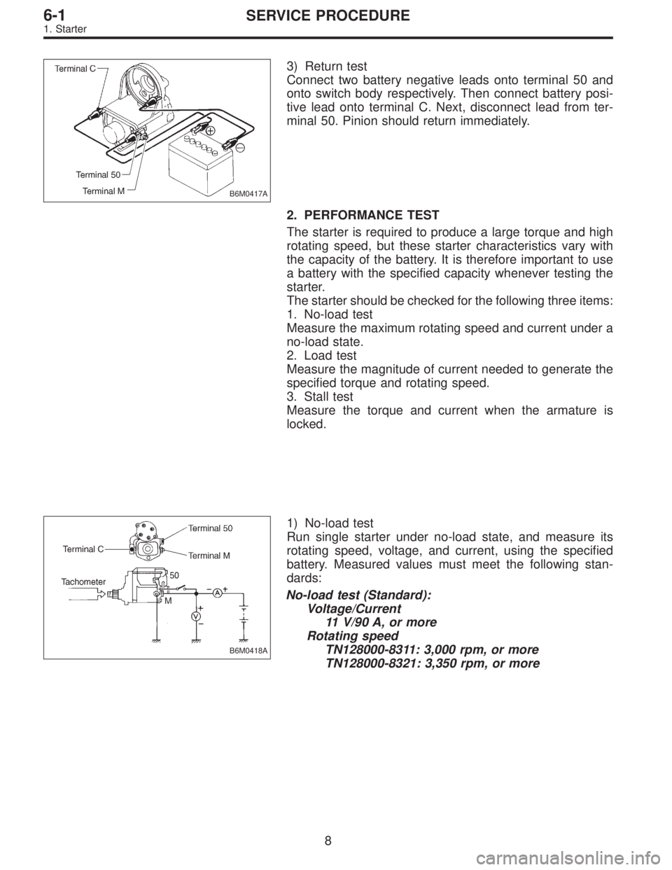
3) Return test
Connect two battery negative leads onto terminal 50 and
onto switch body respectively. Then connect battery posi-
tive lead onto terminal C. Next, disconnect lead from ter-
minal 50. Pinion should return immediately.
2. PERFORMANCE TEST
The starter is required to produce a large torque and high
rotating speed, but these starter characteristics vary with
the capacity of the battery. It is therefore important to use
a battery with the specified capacity whenever testing the
starter.
The starter should be checked for the following three items:
1. No-load test
Measure the maximum rotating speed and current under a
no-load state.
2. Load test
Measure the magnitude of current needed to generate the
specified torque and rotating speed.
3. Stall test
Measure the torque and current when the armature is
locked.
B6M0418A
1) No-load test
Run single starter under no-load state, and measure its
rotating speed, voltage, and current, using the specified
battery. Measured values must meet the following stan-
dards:
No-load test (Standard):
Voltage/Current
11 V/90 A, or more
Rotating speed
TN128000-8311: 3,000 rpm, or more
TN128000-8321: 3,350 rpm, or more
8
6-1SERVICE PROCEDURE
1. Starter