Page 1756 of 3342
B6M0342
With TCS model
1) Disconnect connector of stop light switch from body
harness.
2) Check continuity between terminals when push rod is
pushed in 1.2 to 3.2 mm (0.047 to 0.126 in) from end of
outer case.
Terminal
Switch position1234
When push rod is
pushed in.��
When push rod is
released.��
2. COMBINATION SWITCH (ON-CAR)
Refer to 6-2 [W4D1] as for inspection of combination
switch.
G6M0112
3. TAIL AND ILLUMINATION RELAY
Check continuity between terminals as indicated in table
below, when connecting battery to terminal No. 1 and No. 3
When current flows.Between terminals
No. 2 and No. 4Continuity exists.
When current does not flow.Between terminals
No. 2 and No. 4Continuity does not
exist.
Between terminals
No. 1 and No. 3Continuity exists.
18
6-2SERVICE PROCEDURE
5. Stop and Tail Light
Page 1767 of 3342
B6M0163
2. WIPER MOTOR
1) Check wiper motor operation at low speed.
Connect battery to wiper motor. Check wiper motor for
proper operation at low speed.
B6M0164
2) Check wiper motor operation at high speed.
Connect battery to wiper motor. Check wiper motor for
proper operation at high speed.
B6M0165
3) Check wiper motor for proper stoppage.
Connect battery to wiper motor. After operating wiper motor
at low speed, disconnect battery to stop it.
B6M0166
4) Reconnect battery and ensure that wiper motor stops at
“AUTO STOP”after operating at low speed.
B6M0111
3. WASHER MOTOR
Apply battery voltage between terminals of washer motor
connector and check that washer motor operates.
27
6-2SERVICE PROCEDURE
10. Front Wiper and Washer
Page 1770 of 3342
D: INSPECTION
1. COMBINATION SWITCH (ON-CAR)
1) Remove instrument panel lower cover.
2) Remove lower column cover.
B6M0238
3) Unfasten holddown clip which secures harness, and
disconnect connectors from body harness.
4) Set rear wiper and washer switch to each position and
check continuity between terminals as indicated in table
below:
Terminal
Switch positiond-2 d-1 d-3
WASH��
OFF
ON��
WASH���
B6M0167
2. WIPER MOTOR
1) Operational check
Connect battery to wiper motor and check operation of
wiper motor.
B6M0168
2) Check wiper motor for proper stoppage.
After operating wiper motor, disconnect battery from wiper
motor.
30
6-2SERVICE PROCEDURE
11. Rear Wiper and Washer
Page 1771 of 3342
B6M0169
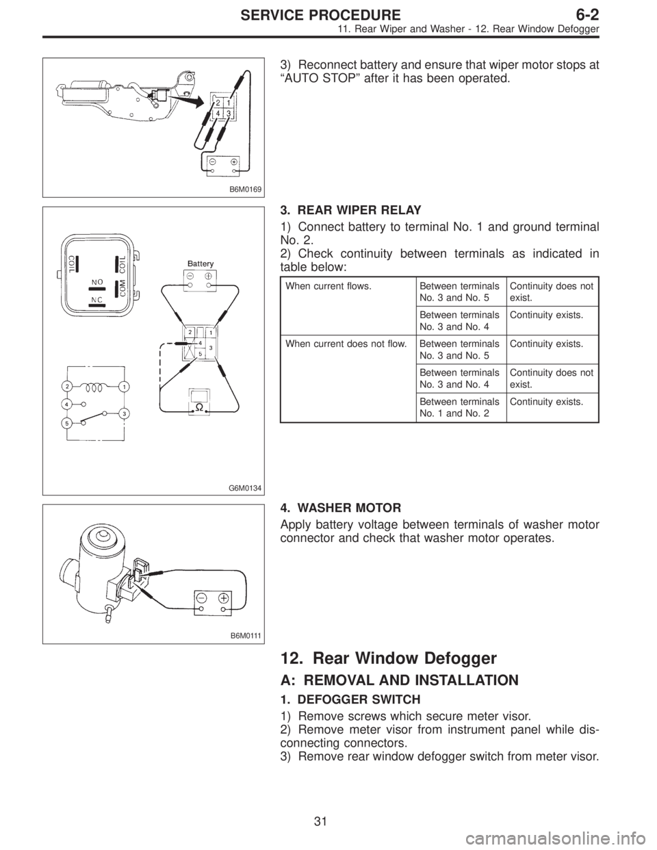
3) Reconnect battery and ensure that wiper motor stops at
“AUTO STOP”after it has been operated.
G6M0134
3. REAR WIPER RELAY
1) Connect battery to terminal No. 1 and ground terminal
No. 2.
2) Check continuity between terminals as indicated in
table below:
When current flows. Between terminals
No. 3 and No. 5Continuity does not
exist.
Between terminals
No. 3 and No. 4Continuity exists.
When current does not flow. Between terminals
No. 3 and No. 5Continuity exists.
Between terminals
No. 3 and No. 4Continuity does not
exist.
Between terminals
No. 1 and No. 2Continuity exists.
B6M0111
4. WASHER MOTOR
Apply battery voltage between terminals of washer motor
connector and check that washer motor operates.
12. Rear Window Defogger
A: REMOVAL AND INSTALLATION
1. DEFOGGER SWITCH
1) Remove screws which secure meter visor.
2) Remove meter visor from instrument panel while dis-
connecting connectors.
3) Remove rear window defogger switch from meter visor.
31
6-2SERVICE PROCEDURE
11. Rear Wiper and Washer - 12. Rear Window Defogger
Page 1772 of 3342
B6M0169
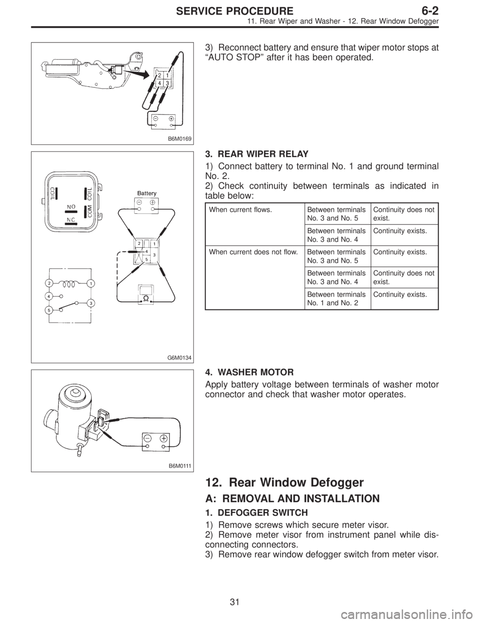
3) Reconnect battery and ensure that wiper motor stops at
“AUTO STOP”after it has been operated.
G6M0134
3. REAR WIPER RELAY
1) Connect battery to terminal No. 1 and ground terminal
No. 2.
2) Check continuity between terminals as indicated in
table below:
When current flows. Between terminals
No. 3 and No. 5Continuity does not
exist.
Between terminals
No. 3 and No. 4Continuity exists.
When current does not flow. Between terminals
No. 3 and No. 5Continuity exists.
Between terminals
No. 3 and No. 4Continuity does not
exist.
Between terminals
No. 1 and No. 2Continuity exists.
B6M0111
4. WASHER MOTOR
Apply battery voltage between terminals of washer motor
connector and check that washer motor operates.
12. Rear Window Defogger
A: REMOVAL AND INSTALLATION
1. DEFOGGER SWITCH
1) Remove screws which secure meter visor.
2) Remove meter visor from instrument panel while dis-
connecting connectors.
3) Remove rear window defogger switch from meter visor.
31
6-2SERVICE PROCEDURE
11. Rear Wiper and Washer - 12. Rear Window Defogger
Page 1773 of 3342
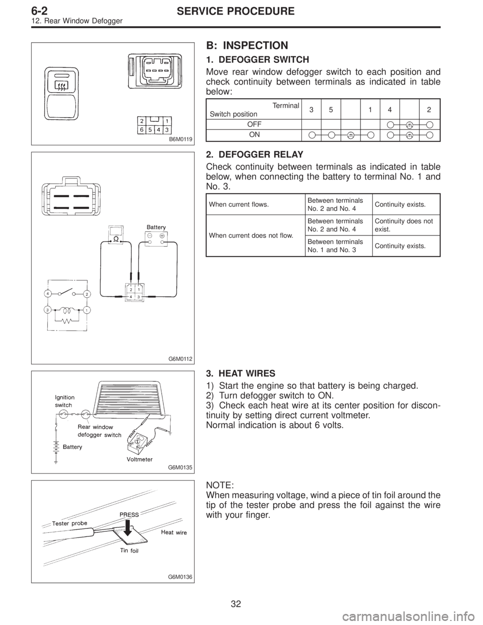
B6M0119
B: INSPECTION
1. DEFOGGER SWITCH
Move rear window defogger switch to each position and
check continuity between terminals as indicated in table
below:
Terminal
Switch position35 14 2
OFF�
�
ON�����
G6M0112
2. DEFOGGER RELAY
Check continuity between terminals as indicated in table
below, when connecting the battery to terminal No. 1 and
No. 3.
When current flows.Between terminals
No. 2 and No. 4Continuity exists.
When current does not flow.Between terminals
No. 2 and No. 4Continuity does not
exist.
Between terminals
No. 1 and No. 3Continuity exists.
G6M0135
3. HEAT WIRES
1) Start the engine so that battery is being charged.
2) Turn defogger switch to ON.
3) Check each heat wire at its center position for discon-
tinuity by setting direct current voltmeter.
Normal indication is about 6 volts.
G6M0136
NOTE:
When measuring voltage, wind a piece of tin foil around the
tip of the tester probe and press the foil against the wire
with your finger.
32
6-2SERVICE PROCEDURE
12. Rear Window Defogger
Page 1780 of 3342
B: INSPECTION
1. HORN SWITCH
Ensure that horn switch is free from the following defects:
1) Burned or shorted contacts
2) Broken or weak spring
3) Damaged harness
4) Worn or corroded mating surface of horn plate
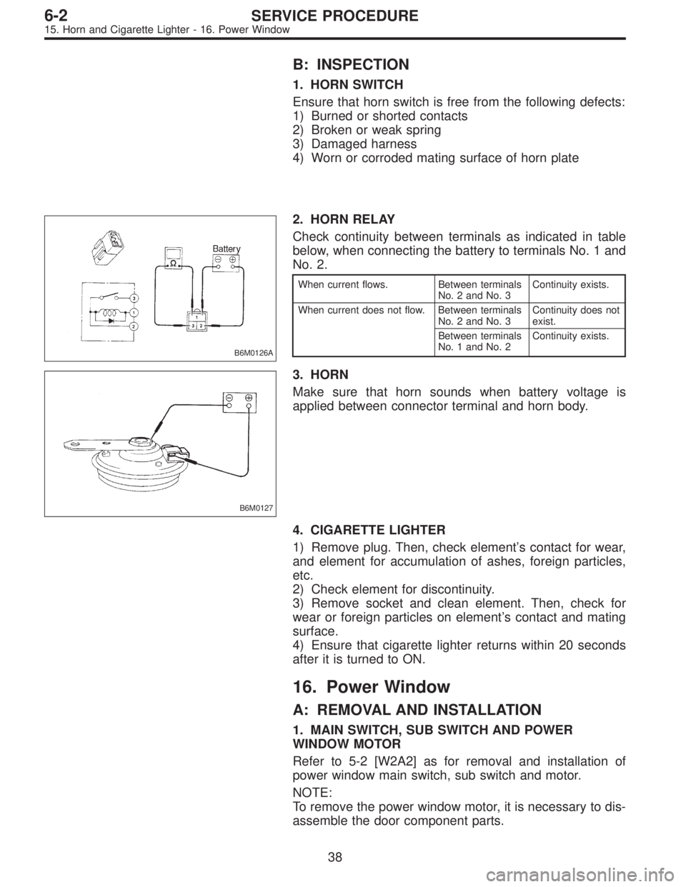
B6M0126A
2. HORN RELAY
Check continuity between terminals as indicated in table
below, when connecting the battery to terminals No. 1 and
No. 2.
When current flows. Between terminals
No. 2 and No. 3Continuity exists.
When current does not flow. Between terminals
No. 2 and No. 3Continuity does not
exist.
Between terminals
No. 1 and No. 2Continuity exists.
B6M0127
3. HORN
Make sure that horn sounds when battery voltage is
applied between connector terminal and horn body.
4. CIGARETTE LIGHTER
1) Remove plug. Then, check element’s contact for wear,
and element for accumulation of ashes, foreign particles,
etc.
2) Check element for discontinuity.
3) Remove socket and clean element. Then, check for
wear or foreign particles on element’s contact and mating
surface.
4) Ensure that cigarette lighter returns within 20 seconds
after it is turned to ON.
16. Power Window
A: REMOVAL AND INSTALLATION
1. MAIN SWITCH, SUB SWITCH AND POWER
WINDOW MOTOR
Refer to 5-2 [W2A2] as for removal and installation of
power window main switch, sub switch and motor.
NOTE:
To remove the power window motor, it is necessary to dis-
assemble the door component parts.
38
6-2SERVICE PROCEDURE
15. Horn and Cigarette Lighter - 16. Power Window
Page 1781 of 3342
B: INSPECTION
1. HORN SWITCH
Ensure that horn switch is free from the following defects:
1) Burned or shorted contacts
2) Broken or weak spring
3) Damaged harness
4) Worn or corroded mating surface of horn plate
B6M0126A
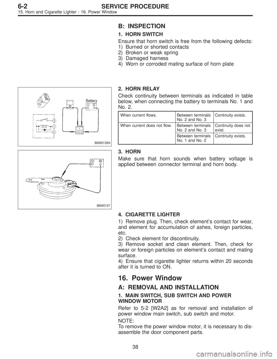
2. HORN RELAY
Check continuity between terminals as indicated in table
below, when connecting the battery to terminals No. 1 and
No. 2.
When current flows. Between terminals
No. 2 and No. 3Continuity exists.
When current does not flow. Between terminals
No. 2 and No. 3Continuity does not
exist.
Between terminals
No. 1 and No. 2Continuity exists.
B6M0127
3. HORN
Make sure that horn sounds when battery voltage is
applied between connector terminal and horn body.
4. CIGARETTE LIGHTER
1) Remove plug. Then, check element’s contact for wear,
and element for accumulation of ashes, foreign particles,
etc.
2) Check element for discontinuity.
3) Remove socket and clean element. Then, check for
wear or foreign particles on element’s contact and mating
surface.
4) Ensure that cigarette lighter returns within 20 seconds
after it is turned to ON.
16. Power Window
A: REMOVAL AND INSTALLATION
1. MAIN SWITCH, SUB SWITCH AND POWER
WINDOW MOTOR
Refer to 5-2 [W2A2] as for removal and installation of
power window main switch, sub switch and motor.
NOTE:
To remove the power window motor, it is necessary to dis-
assemble the door component parts.
38
6-2SERVICE PROCEDURE
15. Horn and Cigarette Lighter - 16. Power Window