Page 1792 of 3342

B6M0162
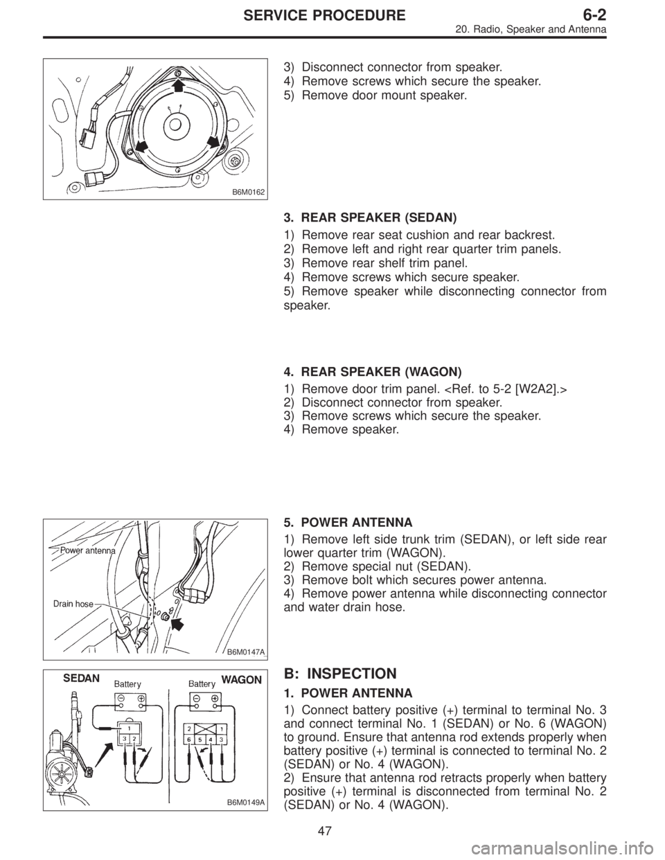
3) Disconnect connector from speaker.
4) Remove screws which secure the speaker.
5) Remove door mount speaker.
3. REAR SPEAKER (SEDAN)
1) Remove rear seat cushion and rear backrest.
2) Remove left and right rear quarter trim panels.
3) Remove rear shelf trim panel.
4) Remove screws which secure speaker.
5) Remove speaker while disconnecting connector from
speaker.
4. REAR SPEAKER (WAGON)
1) Remove door trim panel.
2) Disconnect connector from speaker.
3) Remove screws which secure the speaker.
4) Remove speaker.
B6M0147A
5. POWER ANTENNA
1) Remove left side trunk trim (SEDAN), or left side rear
lower quarter trim (WAGON).
2) Remove special nut (SEDAN).
3) Remove bolt which secures power antenna.
4) Remove power antenna while disconnecting connector
and water drain hose.
B6M0149A
B: INSPECTION
1. POWER ANTENNA
1) Connect battery positive (+) terminal to terminal No. 3
and connect terminal No. 1 (SEDAN) or No. 6 (WAGON)
to ground. Ensure that antenna rod extends properly when
battery positive (+) terminal is connected to terminal No. 2
(SEDAN) or No. 4 (WAGON).
2) Ensure that antenna rod retracts properly when battery
positive (+) terminal is disconnected from terminal No. 2
(SEDAN) or No. 4 (WAGON).
47
6-2SERVICE PROCEDURE
20. Radio, Speaker and Antenna
Page 1795 of 3342
B6M0358
3) Remove nuts which secure actuator.
4) Remove actuator while disconnecting vacuum hose.
Tightening torque:
7.4±1.5 N⋅m (0.75±0.15 kg-m, 5.4±1.1 ft-lb)
B6M0359A
4. VACUUM PUMP AND VALVES
1) Disconnect connector from vacuum pump.
2) Remove bolts which secure vacuum pump.
3) Remove A/C receiver/drier bracket.
4) Remove vacuum pump while disconnecting vacuum
hose.
Tightening torque:
7.4±1.5 N⋅m (0.75±0.15 kg-m, 5.4±1.1 ft-lb)
5. STOP AND BRAKE SWITCH
Refer to 4-5 [C101] (MT) or 4-5 [C201] (AT) as for removal
and installation of stop and brake switch.
6. CLUTCH SWITCH (MT)
Refer to 4-5 [C101] as for removal and installation of clutch
switch.
7. INHIBITOR SWITCH (AT)
Refer to 3-2 [W4A3] as for removal and installation of
inhibitor switch.
G6M0095
8. CRUISE CONTROL MODULE
1) Disconnect battery ground cable.
B3M0377A
2) Remove lower cover and then disconnect connector.
50
6-2SERVICE PROCEDURE
21. Cruise Control
Page 1802 of 3342

B6M0375A
B: INSPECTION
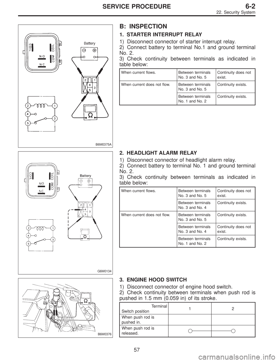
1. STARTER INTERRUPT RELAY
1) Disconnect connector of starter interrupt relay.
2) Connect battery to terminal No.1 and ground terminal
No. 2.
3) Check continuity between terminals as indicated in
table below:
When current flows. Between terminals
No. 3 and No. 5Continuity does not
exist.
When current does not flow. Between terminals
No. 3 and No. 5Continuity exists.
Between terminals
No. 1 and No. 2Continuity exists.
G6M0134
2. HEADLIGHT ALARM RELAY
1) Disconnect connector of headlight alarm relay.
2) Connect battery to terminal No. 1 and ground terminal
No. 2.
3) Check continuity between terminals as indicated in
table below:
When current flows. Between terminals
No. 3 and No. 5Continuity does not
exist.
Between terminals
No. 3 and No. 4Continuity exists.
When current does not flow. Between terminals
No. 3 and No. 5Continuity exists.
Between terminals
No. 3 and No. 4Continuity does not
exist.
Between terminals
No. 1 and No. 2Continuity exists.
B6M0376
3. ENGINE HOOD SWITCH
1) Disconnect connector of engine hood switch.
2) Check continuity between terminals when push rod is
pushed in 1.5 mm (0.059 in) of its stroke.
Terminal
Switch position12
When push rod is
pushed in.
When push rod is
released.��
57
6-2SERVICE PROCEDURE
22. Security System
Page 1809 of 3342
B6M0789A
24. Front Fog Light
A: REMOVAL AND INSTALLATION
1) Disconnect ground cable from battery.
2) Remove the two bolts, then draw out the front fog light
from front bumper.
3) Disconnect the connector.
4) Installation is in the reverse order of removal.
64
6-2SERVICE PROCEDURE
24. Front Fog Light
Page 1810 of 3342
1. Starter Interlock System (MT Model)
A: DIAGNOSTICS PROCEDURE
1. Check main power supply for starter motor.
OK
�Not OK
�Recharge the battery.
�Repair or replace wiring harness.
2. Check power supply for magnet coil of starter
motor.
Not OK
�OK
Repair or replace starter motor.
3. Check power supply for starter interlock relay.
OK
�Not OK
Repair or replace wiring harness.
4. Check starter interlock relay.
OK
�Not OK
Replace starter interlock relay.
5. Check clutch switch.
OK
�Not OK
Adjust or replace clutch switch.
6. Check harness connector between starter
interlock relay and starter motor.
OK
�Not OK
Repair or replace wiring harness.
7. Check harness connector between starter
interlock relay and clutch switch.
OK
�Not OK
Repair or replace wiring harness.
8. Check ground circuit of clutch switch.
OK
�Not OK
Repair or replace wiring harness.
System is OK
�
�
�
�
�
�
�
�
65
6-2DIAGNOSTICS
1. Starter Interlock System (MT Model)
Page 1811 of 3342

B6M0383A
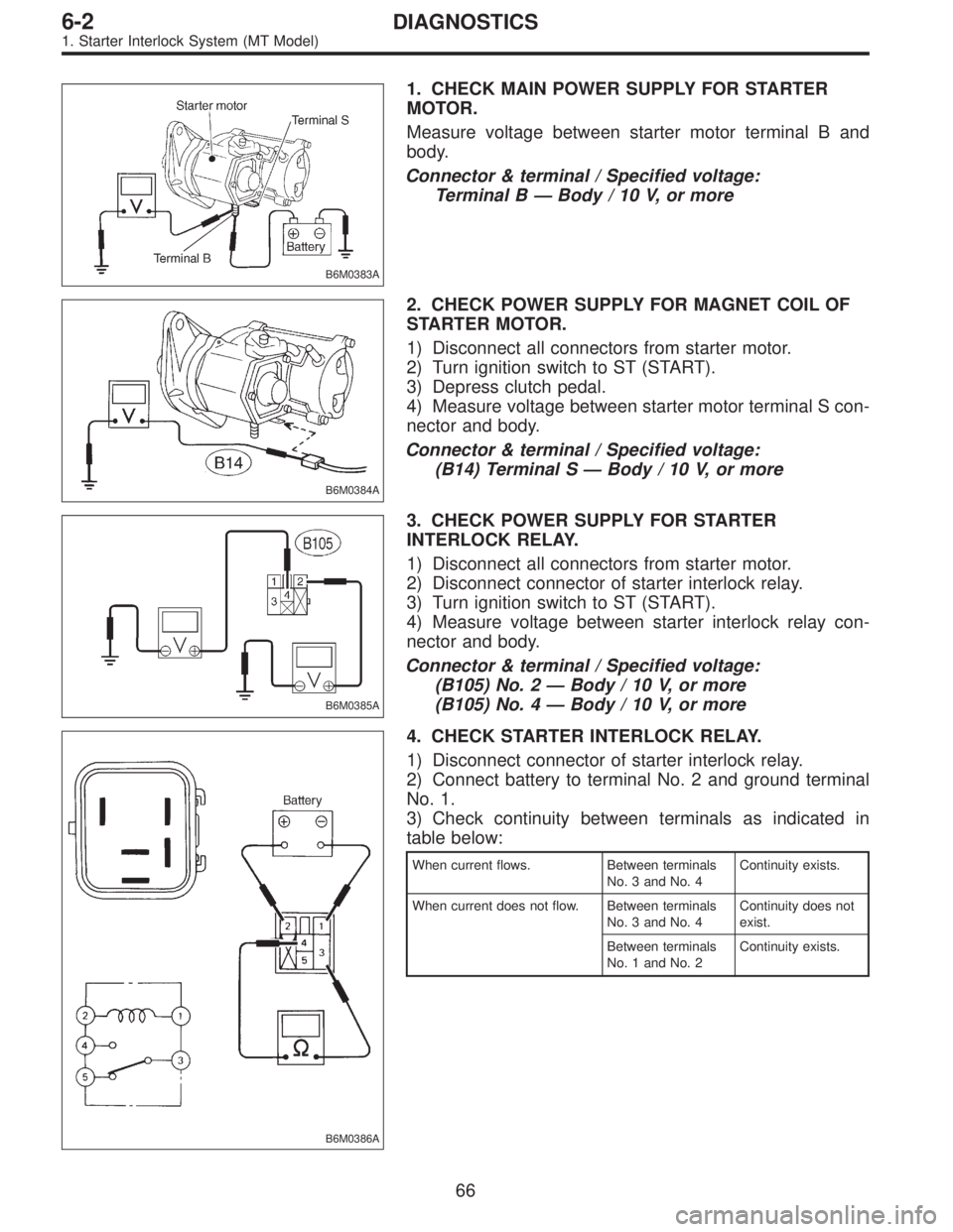
1. CHECK MAIN POWER SUPPLY FOR STARTER
MOTOR.
Measure voltage between starter motor terminal B and
body.
Connector & terminal / Specified voltage:
Terminal B—Body / 10 V, or more
B6M0384A
2. CHECK POWER SUPPLY FOR MAGNET COIL OF
STARTER MOTOR.
1) Disconnect all connectors from starter motor.
2) Turn ignition switch to ST (START).
3) Depress clutch pedal.
4) Measure voltage between starter motor terminal S con-
nector and body.
Connector & terminal / Specified voltage:
(B14) Terminal S—Body / 10 V, or more
B6M0385A
3. CHECK POWER SUPPLY FOR STARTER
INTERLOCK RELAY.
1) Disconnect all connectors from starter motor.
2) Disconnect connector of starter interlock relay.
3) Turn ignition switch to ST (START).
4) Measure voltage between starter interlock relay con-
nector and body.
Connector & terminal / Specified voltage:
(B105) No. 2—Body / 10 V, or more
(B105) No. 4—Body / 10 V, or more
B6M0386A
4. CHECK STARTER INTERLOCK RELAY.
1) Disconnect connector of starter interlock relay.
2) Connect battery to terminal No. 2 and ground terminal
No. 1.
3) Check continuity between terminals as indicated in
table below:
When current flows. Between terminals
No. 3 and No. 4Continuity exists.
When current does not flow. Between terminals
No. 3 and No. 4Continuity does not
exist.
Between terminals
No. 1 and No. 2Continuity exists.
66
6-2DIAGNOSTICS
1. Starter Interlock System (MT Model)
Page 1819 of 3342
3. Combination Meter
A: DIAGNOSTICS PROCEDURE
If speedometer does not operate, or operates abnormally,
check combination meter circuit (shown in flow chart as
described below).
CAUTION:
Make sure that trouble code of vehicle speed sensor 2
system appears in electrical system on-board diagno-
sis.
Speedometer does not operate, or operates
abnormally.
1. Check power supply for combination meter.
OK
�Not OK
�Check for disconnection of the combination meter
connector terminal.
�Check for open circuit between combination meter
and battery.
,Repair or replace wiring harness.
2. Check ground circuit of combination meter.
OK
�Not OK
Repair or replace wiring harness.
3. Check harness connector between
combination meter and vehicle speed sensor
2.
OK
�Not OK
Repair or replace wiring harness.
4. Check vehicle speed sensor 2.
OK
�Not OK
Replace vehicle speed sensor 2.
Failure of the speedometer.
�
�
�
�
�
74
6-2DIAGNOSTICS
3. Combination Meter
Page 1823 of 3342

B6M0391A
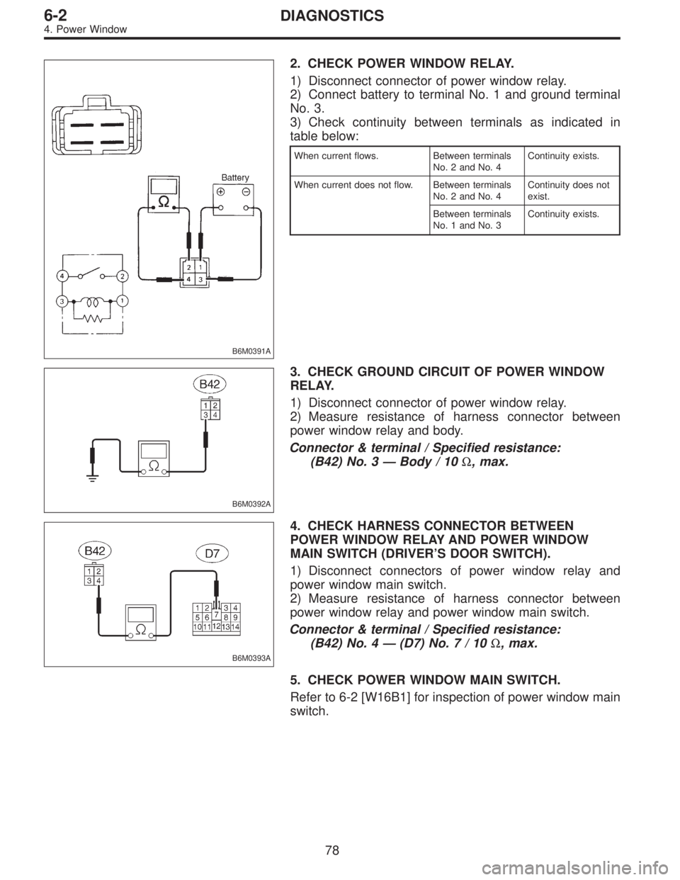
2. CHECK POWER WINDOW RELAY.
1) Disconnect connector of power window relay.
2) Connect battery to terminal No. 1 and ground terminal
No. 3.
3) Check continuity between terminals as indicated in
table below:
When current flows. Between terminals
No. 2 and No. 4Continuity exists.
When current does not flow. Between terminals
No. 2 and No. 4Continuity does not
exist.
Between terminals
No. 1 and No. 3Continuity exists.
B6M0392A
3. CHECK GROUND CIRCUIT OF POWER WINDOW
RELAY.
1) Disconnect connector of power window relay.
2) Measure resistance of harness connector between
power window relay and body.
Connector & terminal / Specified resistance:
(B42) No. 3—Body / 10Ω, max.
B6M0393A
4. CHECK HARNESS CONNECTOR BETWEEN
POWER WINDOW RELAY AND POWER WINDOW
MAIN SWITCH (DRIVER’S DOOR SWITCH).
1) Disconnect connectors of power window relay and
power window main switch.
2) Measure resistance of harness connector between
power window relay and power window main switch.
Connector & terminal / Specified resistance:
(B42) No. 4—(D7) No.7/10Ω, max.
5. CHECK POWER WINDOW MAIN SWITCH.
Refer to 6-2 [W16B1] for inspection of power window main
switch.
78
6-2DIAGNOSTICS
4. Power Window