Page 1909 of 3342
51. READ DATA FUNCTION KEY LIST FOR AT
Function mode Contents Abbr. Unit
F00 Mode display E-4AT—
F01 Battery voltage VB V
F02 Vehicle speed sensor 1 signal VSP1 m/h
F03 Vehicle speed sensor 1 signal VSP1 km/h
F04 Vehicle speed sensor 2 signal VSP2 m/h
F05 Vehicle speed sensor 2 signal VSP2 km/h
F06 Engine speed EREV rpm
F07 ATF temperature sensor signal ATFT deg F
F08 ATF temperature sensor signal ATFT deg C
F09 Throttle position sensor signal THV V
F10 Gear position GEAR—
F11 Line pressure duty ratio PLDTY %
F12 Lock-up duty ratio LUDTY %
F13 AWD duty ratio 4WDTY %
F14 Throttle position sensor power supply voltage THVCC V
F15 Mass air flow sensor signal AFM V
58
2-7ON-BOARD DIAGNOSTICS II SYSTEM
3. Diagnosis System
Page 1910 of 3342
B2M1046
52. FUNCTION MODE: F00
—MODE DISPLAY—
SPECIFIED DATA:
Data at the left should be indicated.
Probable cause (if outside“specified data”)
1. Communication failure
(No communication method can be confirmed
with power ON.)
�(1)Check loose or poor connectors, or
shortcircuit.
(2) Check type of cartridge.
2. Vehicle types cannot be identified (due to
communication failure).�Check improper cartridge.
Replace with proper one.
OBD0673
53. FUNCTION MODE: F01
—BATTERY VOLTAGE (VB)—
CONDITION:
(1) Ignition switch ON
(2) Engine idling after warm-up
SPECIFIED DATA:
(1) 12±1 V
(2) 13±1 V
1. Battery�Check battery voltage and specific gravity of
electrolyte.
2. Charging system�(1)Measure regulating voltage under no loads.
(2) Check generator (as a single unit).
59
2-7ON-BOARD DIAGNOSTICS II SYSTEM
3. Diagnosis System
Page 1916 of 3342
G3M0151
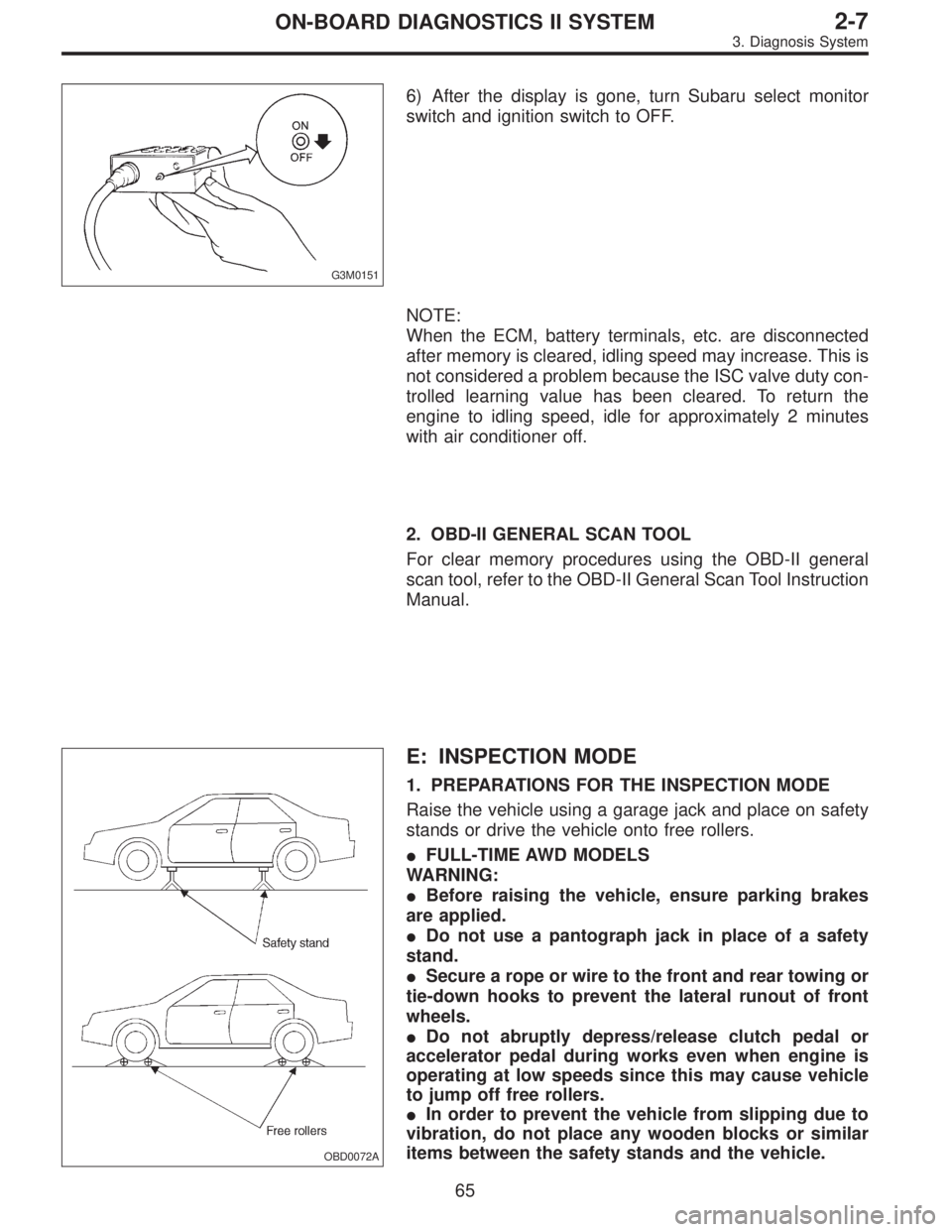
6) After the display is gone, turn Subaru select monitor
switch and ignition switch to OFF.
NOTE:
When the ECM, battery terminals, etc. are disconnected
after memory is cleared, idling speed may increase. This is
not considered a problem because the ISC valve duty con-
trolled learning value has been cleared. To return the
engine to idling speed, idle for approximately 2 minutes
with air conditioner off.
2. OBD-II GENERAL SCAN TOOL
For clear memory procedures using the OBD-II general
scan tool, refer to the OBD-II General Scan Tool Instruction
Manual.
OBD0072A
E: INSPECTION MODE
1. PREPARATIONS FOR THE INSPECTION MODE
Raise the vehicle using a garage jack and place on safety
stands or drive the vehicle onto free rollers.
�FULL-TIME AWD MODELS
WARNING:
�Before raising the vehicle, ensure parking brakes
are applied.
�Do not use a pantograph jack in place of a safety
stand.
�Secure a rope or wire to the front and rear towing or
tie-down hooks to prevent the lateral runout of front
wheels.
�Do not abruptly depress/release clutch pedal or
accelerator pedal during works even when engine is
operating at low speeds since this may cause vehicle
to jump off free rollers.
�In order to prevent the vehicle from slipping due to
vibration, do not place any wooden blocks or similar
items between the safety stands and the vehicle.
65
2-7ON-BOARD DIAGNOSTICS II SYSTEM
3. Diagnosis System
Page 1927 of 3342
4. Cautions
A: SUPPLEMENTAL RESTRAINT SYSTEM
“AIRBAG”
Airbag system wiring harness is routed near the engine
control module (ECM), main relay and fuel pump relay.
CAUTION:
�All Airbag system wiring harness and connectors
are colored yellow. Do not use electrical test equip-
ment on these circuit.
�Be careful not to damage Airbag system wiring har-
ness when servicing the engine control module (ECM),
transmission control module (TCM), main relay and
fuel pump relay.
B: PRECAUTIONS
1) Never connect the battery in reverse polarity.
�The ECM will be destroyed instantly.
�The fuel injector and other part will be damaged in just
a few minutes more.
2) Do not disconnect the battery terminals while the
engine is running.
�A large counter electromotive force will be generated in
the alternator, and this voltage may damage electronic
parts such as ECM, etc.
3) Before disconnecting the connectors of each sensor
and the ECM, be sure to turn OFF the ignition switch.
4) Before removing ECM from the located position, dis-
connect two cables on battery.
�Otherwise, the ECM may be damaged.
5) The connectors to each sensor in the engine compart-
ment and the harness connectors on the engine side and
body side are all designed to be waterproof. However, it is
still necessary to take care not to allow water to get into the
connectors when washing the vehicle, or when servicing
the vehicle on a rainy day.
H2M1154A
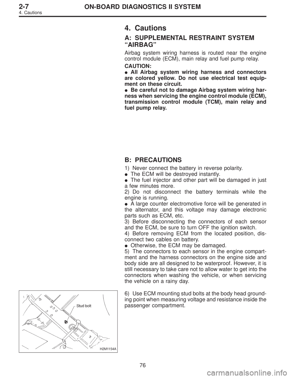
6) Use ECM mounting stud bolts at the body head ground-
ing point when measuring voltage and resistance inside the
passenger compartment.
76
2-7ON-BOARD DIAGNOSTICS II SYSTEM
4. Cautions
Page 1929 of 3342
14) In AT vehicles, do not continue the stall for more than
five seconds at a time (from closed throttle, fully open
throttle to stall engine speed).
15) On ABS or ABS/TCS vehicle, when performing driving
test in jacked-up or lifted-up position, sometimes the warn-
ing light may be lit, but this is not a malfunction of the sys-
tem. The reason for this is the speed difference between
the front and rear wheels. After diagnosis of engine control
system, perform the ABS or ABS/TCS memory clearance
procedure of self-diagnosis system.
[T9K0], or 4-4c [T6D2] or [T9J0], or 4-4d [T6D2] or [T9J0].>
C: PRE-INSPECTION
Before performing diagnostics, check the following items
which might affect engine problems:
1. POWER SUPPLY
1) Measure battery voltage and specific gravity of electro-
lyte.
Standard voltage: 12 V
Specific gravity: Above 1.260
2) Check the condition of the main and other fuses, and
harnesses and connectors. Also check for proper ground-
ing.
B2M0648A
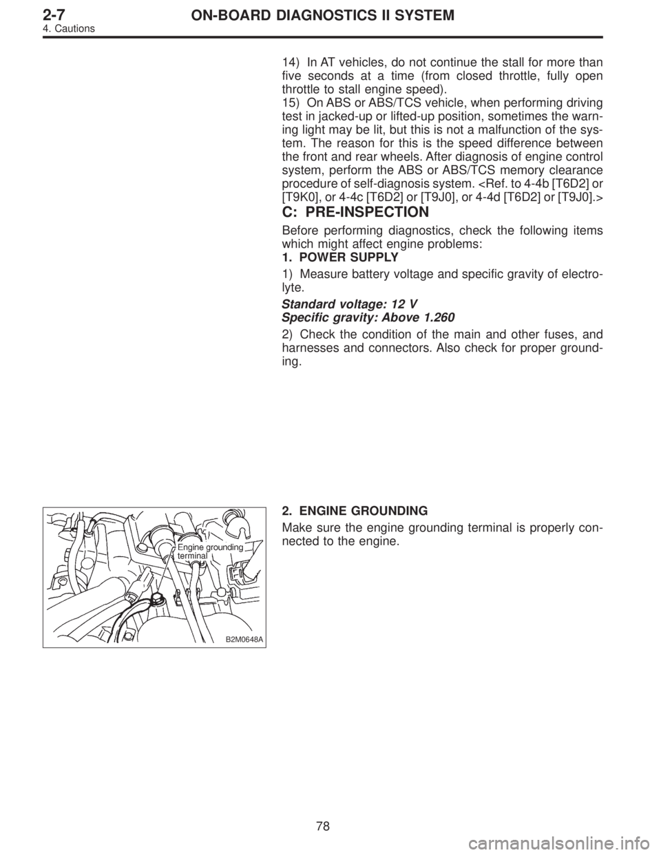
2. ENGINE GROUNDING
Make sure the engine grounding terminal is properly con-
nected to the engine.
78
2-7ON-BOARD DIAGNOSTICS II SYSTEM
4. Cautions
Page 1949 of 3342
OBD0100A
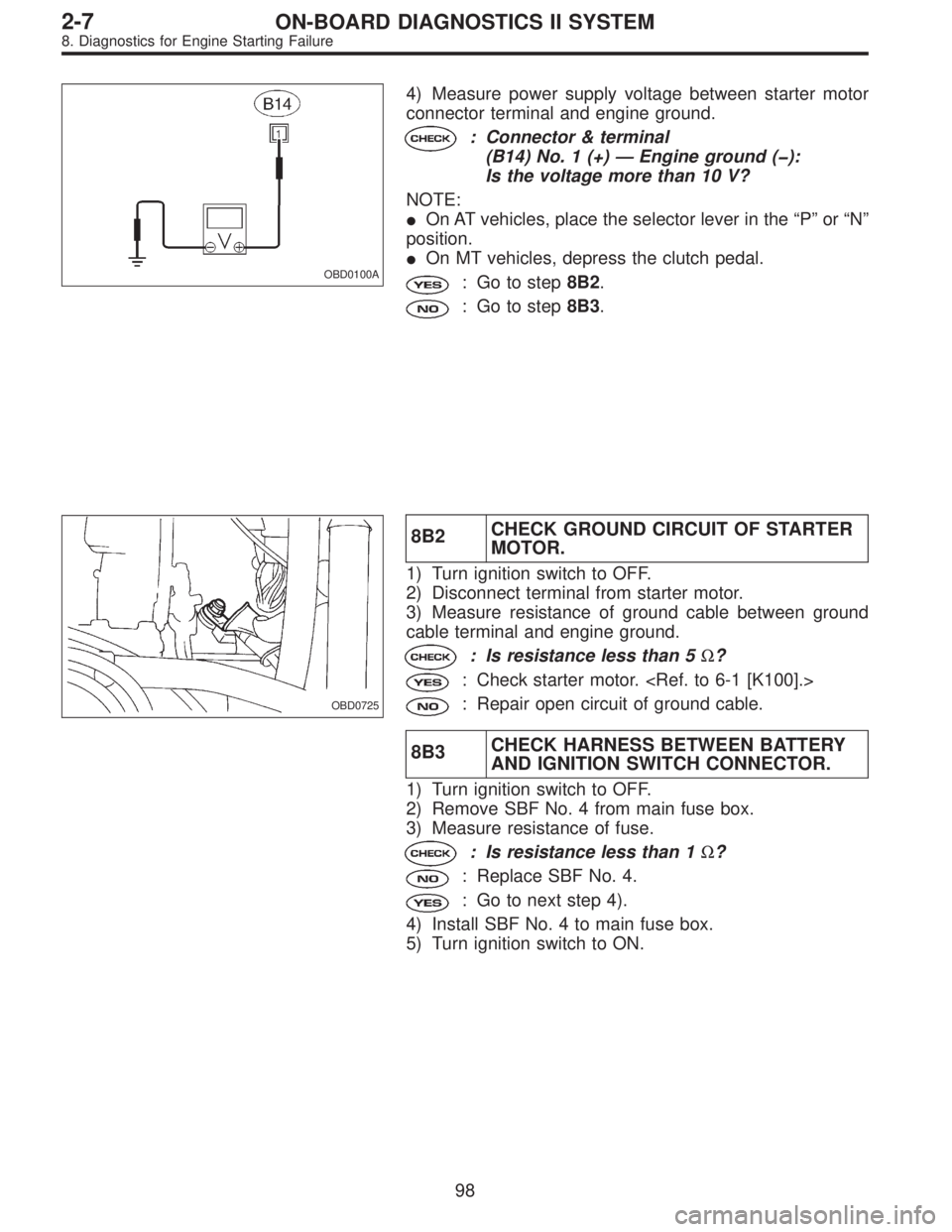
4) Measure power supply voltage between starter motor
connector terminal and engine ground.
: Connector & terminal
(B14) No. 1 (+)—Engine ground (�):
Is the voltage more than 10 V?
NOTE:
�On AT vehicles, place the selector lever in the“P”or“N”
position.
�On MT vehicles, depress the clutch pedal.
: Go to step8B2.
: Go to step8B3.
OBD0725
8B2CHECK GROUND CIRCUIT OF STARTER
MOTOR.
1) Turn ignition switch to OFF.
2) Disconnect terminal from starter motor.
3) Measure resistance of ground cable between ground
cable terminal and engine ground.
: Is resistance less than 5Ω?
: Check starter motor.
: Repair open circuit of ground cable.
8B3CHECK HARNESS BETWEEN BATTERY
AND IGNITION SWITCH CONNECTOR.
1) Turn ignition switch to OFF.
2) Remove SBF No. 4 from main fuse box.
3) Measure resistance of fuse.
: Is resistance less than 1Ω?
: Replace SBF No. 4.
: Go to next step 4).
4) Install SBF No. 4 to main fuse box.
5) Turn ignition switch to ON.
98
2-7ON-BOARD DIAGNOSTICS II SYSTEM
8. Diagnostics for Engine Starting Failure
Page 1955 of 3342
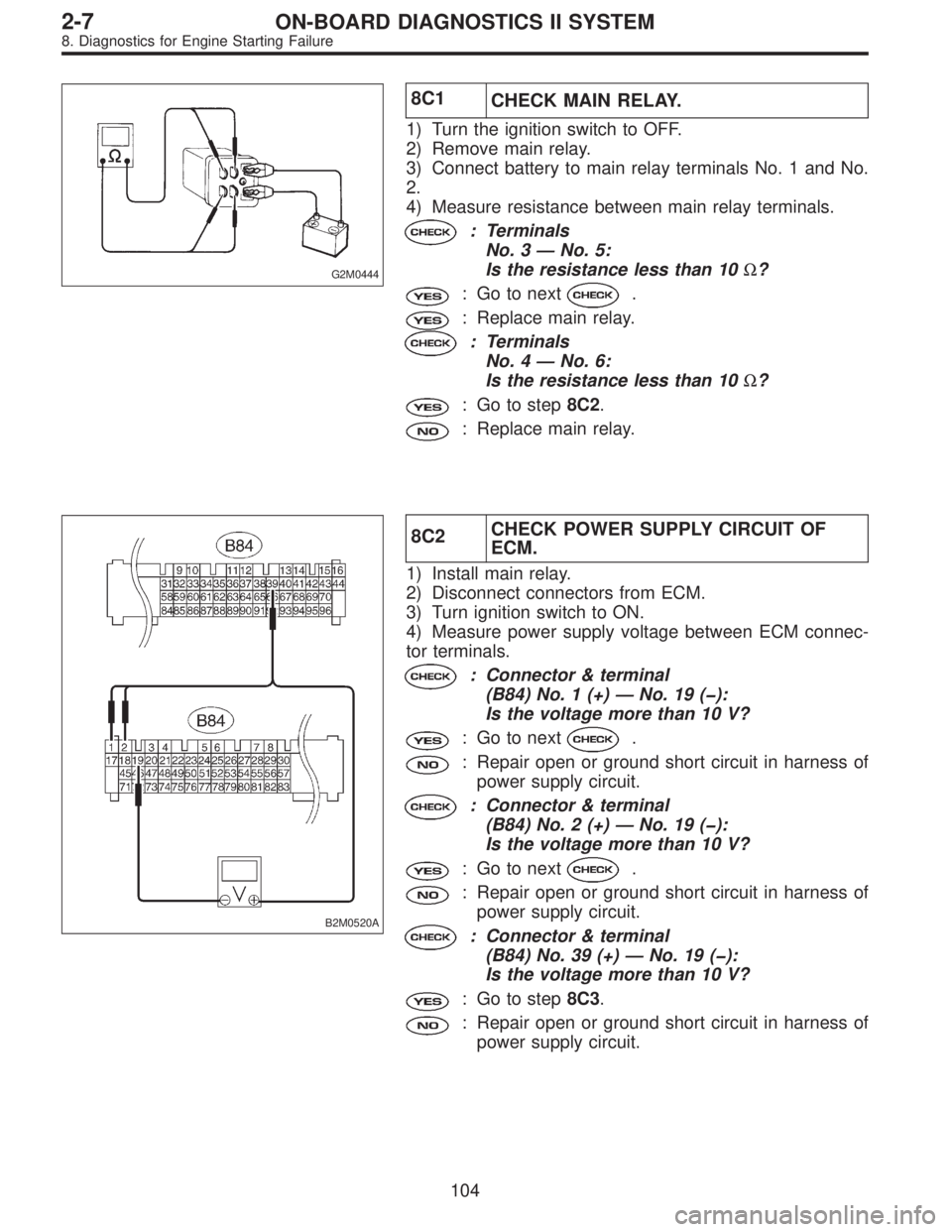
G2M0444
8C1
CHECK MAIN RELAY.
1) Turn the ignition switch to OFF.
2) Remove main relay.
3) Connect battery to main relay terminals No. 1 and No.
2.
4) Measure resistance between main relay terminals.
: Terminals
No. 3—No. 5:
Is the resistance less than 10Ω?
: Go to next.
: Replace main relay.
: Terminals
No. 4—No. 6:
Is the resistance less than 10Ω?
: Go to step8C2.
: Replace main relay.
B2M0520A
8C2CHECK POWER SUPPLY CIRCUIT OF
ECM.
1) Install main relay.
2) Disconnect connectors from ECM.
3) Turn ignition switch to ON.
4) Measure power supply voltage between ECM connec-
tor terminals.
: Connector & terminal
(B84) No. 1 (+)—No. 19 (�):
Is the voltage more than 10 V?
: Go to next.
: Repair open or ground short circuit in harness of
power supply circuit.
: Connector & terminal
(B84) No. 2 (+)—No. 19 (�):
Is the voltage more than 10 V?
: Go to next.
: Repair open or ground short circuit in harness of
power supply circuit.
: Connector & terminal
(B84) No. 39 (+)—No. 19 (�):
Is the voltage more than 10 V?
: Go to step8C3.
: Repair open or ground short circuit in harness of
power supply circuit.
104
2-7ON-BOARD DIAGNOSTICS II SYSTEM
8. Diagnostics for Engine Starting Failure
Page 1965 of 3342

B2M0526A
8E4CHECK HARNESS BETWEEN FUEL
PUMP AND FUEL PUMP RELAY CON-
NECTOR.
1) Turn ignition switch to OFF.
2) Measure resistance of harness connector between fuel
pump and fuel pump relay.
: Connector & terminal
(R58) No. 1—(B46) No. 4:
Is the resistance less than 1Ω?
: Go to next.
: Repair open circuit in harness between fuel pump
and fuel pump relay connector.
: Connector & terminal
(R58) No. 1—Chassis ground:
Is the resistance more than 1 MΩ?
: Go to step8E5.
: Repair short circuit in harness between fuel pump
and fuel pump relay connector.
G2M0461
8E5
CHECK FUEL PUMP RELAY.
1) Disconnect connectors from fuel pump relay and main
relay.
2) Remove fuel pump relay and main relay with bracket.
3) Connect battery to fuel pump relay connector terminals
No. 1 and No. 3.
4) Measure resistance between connector terminals of
fuel pump relay.
: Terminals
No. 2—No. 4:
Is the resistance less than 10Ω?
: Go to step8E6.
: Replace fuel pump relay.
11 4
2-7ON-BOARD DIAGNOSTICS II SYSTEM
8. Diagnostics for Engine Starting Failure