Page 1416 of 3342
B4M1222
E: INSTALLATION
1) Install ABSCM&H/U.
CAUTION:
Confirm that the specifications of the ABSCM&H/U
conforms to the vehicle specifications.
Tightening torque:
18±5 N⋅m (1.8±0.5 kg-m, 13.0±3.6 ft-lb)
2) Connect brake pipes to their correct ABSCM&H/U con-
nections.
3) Using cable clip, secure ABSCM&H/U harness to
bracket.
4) Connect connector to ABSCM&H/U.
CAUTION:
�Be sure to remove all foreign matter from inside the
connector before connecting.
�Ensure that the ABSCM&H/U connector is securely
locked.
5) Install air intake duct.
6) Connect ground cable to battery.
7) Bleed air from the brake system.
23. ABS Sensor (ABS 5.3i Type)
24. G Sensor (ABS 5.3i Type)
130
4-4SERVICE PROCEDURE
22. ABS Control Module and Hydraulic Control Unit (ABSCM&H/U) (ABS 5.3i Type) - 24. G Sensor (ABS 5.3i Type)
Page 1417 of 3342
B4M1222
E: INSTALLATION
1) Install ABSCM&H/U.
CAUTION:
Confirm that the specifications of the ABSCM&H/U
conforms to the vehicle specifications.
Tightening torque:
18±5 N⋅m (1.8±0.5 kg-m, 13.0±3.6 ft-lb)
2) Connect brake pipes to their correct ABSCM&H/U con-
nections.
3) Using cable clip, secure ABSCM&H/U harness to
bracket.
4) Connect connector to ABSCM&H/U.
CAUTION:
�Be sure to remove all foreign matter from inside the
connector before connecting.
�Ensure that the ABSCM&H/U connector is securely
locked.
5) Install air intake duct.
6) Connect ground cable to battery.
7) Bleed air from the brake system.
23. ABS Sensor (ABS 5.3i Type)
24. G Sensor (ABS 5.3i Type)
130
4-4SERVICE PROCEDURE
22. ABS Control Module and Hydraulic Control Unit (ABSCM&H/U) (ABS 5.3i Type) - 24. G Sensor (ABS 5.3i Type)
Page 1428 of 3342

B4M1191A
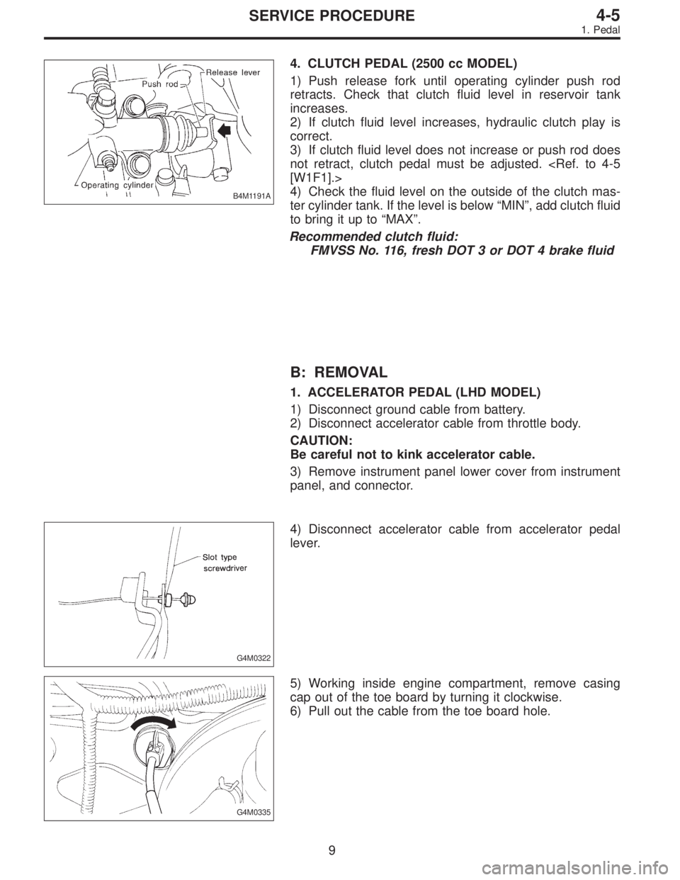
4. CLUTCH PEDAL (2500 cc MODEL)
1) Push release fork until operating cylinder push rod
retracts. Check that clutch fluid level in reservoir tank
increases.
2) If clutch fluid level increases, hydraulic clutch play is
correct.
3) If clutch fluid level does not increase or push rod does
not retract, clutch pedal must be adjusted.
[W1F1].>
4) Check the fluid level on the outside of the clutch mas-
ter cylinder tank. If the level is below“MIN”, add clutch fluid
to bring it up to“MAX”.
Recommended clutch fluid:
FMVSS No. 116, fresh DOT 3 or DOT 4 brake fluid
B: REMOVAL
1. ACCELERATOR PEDAL (LHD MODEL)
1) Disconnect ground cable from battery.
2) Disconnect accelerator cable from throttle body.
CAUTION:
Be careful not to kink accelerator cable.
3) Remove instrument panel lower cover from instrument
panel, and connector.
G4M0322
4) Disconnect accelerator cable from accelerator pedal
lever.
G4M0335
5) Working inside engine compartment, remove casing
cap out of the toe board by turning it clockwise.
6) Pull out the cable from the toe board hole.
9
4-5SERVICE PROCEDURE
1. Pedal
Page 1429 of 3342

G4M0321
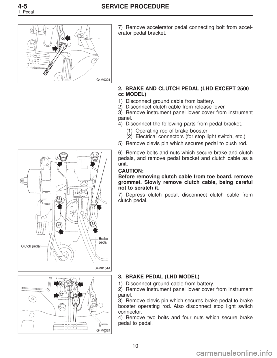
7) Remove accelerator pedal connecting bolt from accel-
erator pedal bracket.
2. BRAKE AND CLUTCH PEDAL (LHD EXCEPT 2500
cc MODEL)
1) Disconnect ground cable from battery.
2) Disconnect clutch cable from release lever.
3) Remove instrument panel lower cover from instrument
panel.
4) Disconnect the following parts from pedal bracket.
(1) Operating rod of brake booster
(2) Electrical connectors (for stop light switch, etc.)
5) Remove clevis pin which secures pedal to push rod.
B4M0154A
6) Remove bolts and nuts which secure brake and clutch
pedals, and remove pedal bracket and clutch cable as a
unit.
CAUTION:
Before removing clutch cable from toe board, remove
grommet. Slowly remove clutch cable, being careful
not to scratch it.
7) Depress clutch pedal, disconnect clutch cable from
clutch pedal.
G4M0324
3. BRAKE PEDAL (LHD MODEL)
1) Disconnect ground cable from battery.
2) Remove instrument panel lower cover from instrument
panel.
3) Remove clevis pin which secures brake pedal to brake
booster operating rod. Also disconnect stop light switch
connector.
4) Remove two bolts and four nuts which secure brake
pedal to pedal.
10
4-5SERVICE PROCEDURE
1. Pedal
Page 1430 of 3342
4. ACCELERATOR AND BRAKE PEDAL (RHD
MODEL)
1) Disconnect negative cable from battery.
2) Disconnect accelerator cable from throttle body.
CAUTION:
Be careful not to kink accelerator cable.
3) Remove instrument panel lower cover from instrument
panel.
4) Remove clevis pin which secures brake pedal to brake
booster operating rod. Also disconnect electrical connec-
tors (for stop light switch, etc.).
G4M0322
5) Disconnect accelerator cable from accelerator pedal
lever.
B4M0156A
6) Remove the casing cap out of the toe board by turning
it clockwise.
7) Pull out the cable from the toe board hole.
11
4-5SERVICE PROCEDURE
1. Pedal
Page 1446 of 3342
1. Supplemental Restraint System
“Airbag”
Airbag system wiring harness is routed near the instrument
panel, heater unit, blower motor and control unit.
CAUTION:
�All Airbag system wiring harness and connectors
are colored yellow. Do not use electrical test equip-
ment on these circuit.
�Be careful not to damage Airbag system wiring har-
ness when servicing the instrument panel, heater unit,
blower motor and control unit.
2. Heater Unit
A: REMOVAL AND INSTALLATION
1) Disconnect GND cable from battery.
2) Remove heater hoses (inlet, outlet) in engine compart-
ment.
NOTE:
Drain as much coolant from heater unit as possible, and
plug disconnected hose with cloth.
3) Remove instrument panel.
4) Remove steering support beam.
5) Remove evaporator. (With A/C model)
G4M0554
6) Remove heater unit.
7
4-6SERVICE PROCEDURE
1. Supplemental Restraint System“Airbag”- 2. Heater Unit
Page 1447 of 3342
1. Supplemental Restraint System
“Airbag”
Airbag system wiring harness is routed near the instrument
panel, heater unit, blower motor and control unit.
CAUTION:
�All Airbag system wiring harness and connectors
are colored yellow. Do not use electrical test equip-
ment on these circuit.
�Be careful not to damage Airbag system wiring har-
ness when servicing the instrument panel, heater unit,
blower motor and control unit.
2. Heater Unit
A: REMOVAL AND INSTALLATION
1) Disconnect GND cable from battery.
2) Remove heater hoses (inlet, outlet) in engine compart-
ment.
NOTE:
Drain as much coolant from heater unit as possible, and
plug disconnected hose with cloth.
3) Remove instrument panel.
4) Remove steering support beam.
5) Remove evaporator. (With A/C model)
G4M0554
6) Remove heater unit.
7
4-6SERVICE PROCEDURE
1. Supplemental Restraint System“Airbag”- 2. Heater Unit
Page 1448 of 3342
7) Installation is in the reverse order of removal.
Fitted length of heater hose over pipe:
25 — 30 mm (0.98 — 1.18 in)
8) Pour coolant.
B5M0025
3. Blower Motor Assembly
A: REMOVAL AND INSTALLATION
1) Disconnect GND cable from battery.
2) Remove glove box and pocket back panel.
[W1A0].>
3) Disconnect blower motor harness connector.
G4M0555
4) Disconnect aspirator pipe�1.
5) Remove blower motor mounting screw.
6) Remove blower motor assembly.
7) Installation is in the reverse order of removal.
8
4-6SERVICE PROCEDURE
2. Heater Unit - 3. Blower Motor Assembly