Page 1247 of 3342
G4M0101
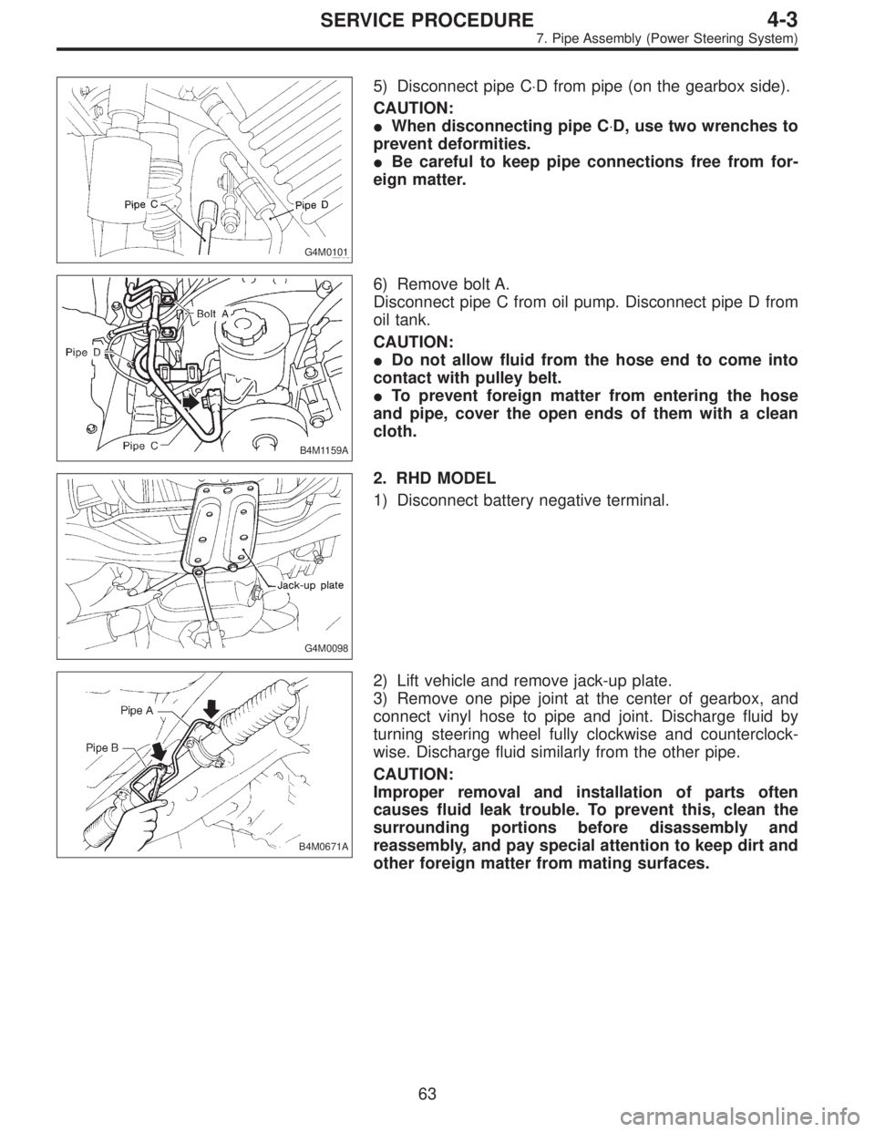
5) Disconnect pipe C⋅D from pipe (on the gearbox side).
CAUTION:
�When disconnecting pipe C⋅D, use two wrenches to
prevent deformities.
�Be careful to keep pipe connections free from for-
eign matter.
B4M1159A
6) Remove bolt A.
Disconnect pipe C from oil pump. Disconnect pipe D from
oil tank.
CAUTION:
�Do not allow fluid from the hose end to come into
contact with pulley belt.
�To prevent foreign matter from entering the hose
and pipe, cover the open ends of them with a clean
cloth.
G4M0098
2. RHD MODEL
1) Disconnect battery negative terminal.
B4M0671A
2) Lift vehicle and remove jack-up plate.
3) Remove one pipe joint at the center of gearbox, and
connect vinyl hose to pipe and joint. Discharge fluid by
turning steering wheel fully clockwise and counterclock-
wise. Discharge fluid similarly from the other pipe.
CAUTION:
Improper removal and installation of parts often
causes fluid leak trouble. To prevent this, clean the
surrounding portions before disassembly and
reassembly, and pay special attention to keep dirt and
other foreign matter from mating surfaces.
63
4-3SERVICE PROCEDURE
7. Pipe Assembly (Power Steering System)
Page 1250 of 3342
B4M0557A
6) Temporarily install clamp E on pipes C and D.
CAUTION:
Ensure that the letter“8”on each clamp side are
diagonally opposite each other as shown in the figure.
7) Tighten clamp E firmly.
Tightening torque:
7.4±2.0 N⋅m (0.75±0.20 kg-m, 5.4±1.4 ft-lb)
8) Tighten joint nut.
Tightening torque:
15±5 N⋅m (1.5±0.5 kg-m, 10.8±3.6 ft-lb)
G4M0099
9) Connect pipes A and B to four pipe joints of gearbox.
Connect upper pipe B first, and lower pipe A second.
Tightening torque:
13±3 N⋅m (1.3±0.3 kg-m, 9.4±2.2 ft-lb)
10) Install jack-up plate.
11) Connect battery minus terminal.
12) Feed the specified fluid and discharge air.
NOTE:
Never start the engine before feeding the fluid; otherwise
vane pump might be seized up.
66
4-3SERVICE PROCEDURE
7. Pipe Assembly (Power Steering System)
Page 1253 of 3342
10) Install jack-up plate.
11) Connect battery negative terminal.
12) Feed the specified fluid and discharge air.
NOTE:
Never start the engine before feeding the fluid; otherwise
vane pump might be seized up.
B4M0674A
69
4-3SERVICE PROCEDURE
7. Pipe Assembly (Power Steering System)
Page 1254 of 3342
B4M1160
8. Oil Pump (Power Steering System)
A: REMOVAL
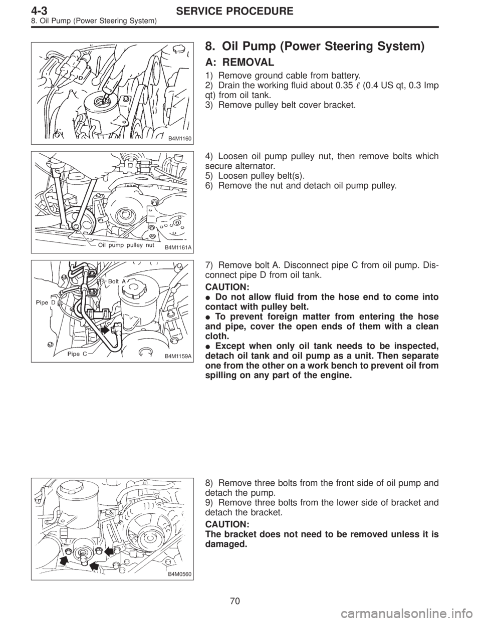
1) Remove ground cable from battery.
2) Drain the working fluid about 0.35�(0.4 US qt, 0.3 Imp
qt) from oil tank.
3) Remove pulley belt cover bracket.
B4M1161A
4) Loosen oil pump pulley nut, then remove bolts which
secure alternator.
5) Loosen pulley belt(s).
6) Remove the nut and detach oil pump pulley.
B4M1159A
7) Remove bolt A. Disconnect pipe C from oil pump. Dis-
connect pipe D from oil tank.
CAUTION:
�Do not allow fluid from the hose end to come into
contact with pulley belt.
�To prevent foreign matter from entering the hose
and pipe, cover the open ends of them with a clean
cloth.
�Except when only oil tank needs to be inspected,
detach oil tank and oil pump as a unit. Then separate
one from the other on a work bench to prevent oil from
spilling on any part of the engine.
B4M0560
8) Remove three bolts from the front side of oil pump and
detach the pump.
9) Remove three bolts from the lower side of bracket and
detach the bracket.
CAUTION:
The bracket does not need to be removed unless it is
damaged.
70
4-3SERVICE PROCEDURE
8. Oil Pump (Power Steering System)
Page 1263 of 3342
B4M1163A
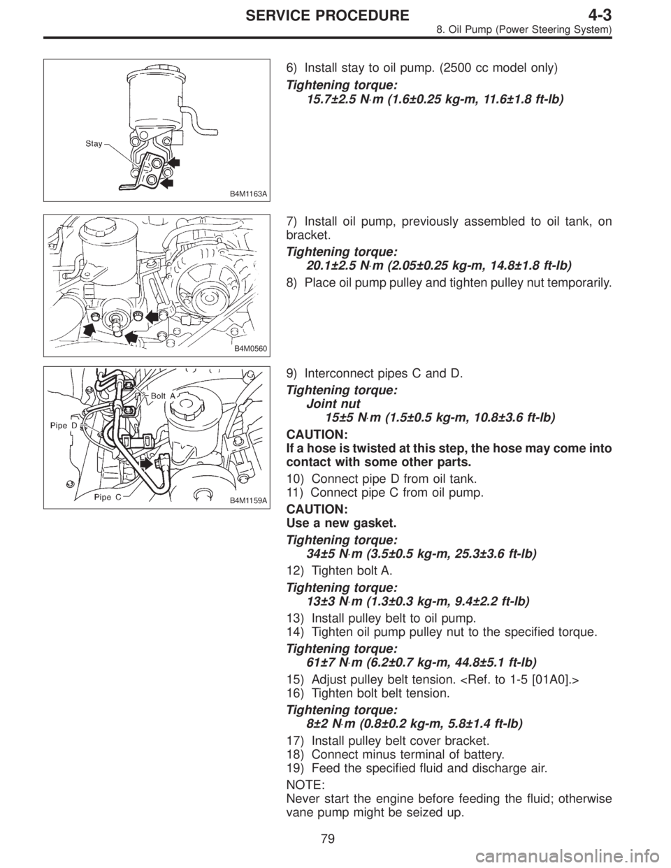
6) Install stay to oil pump. (2500 cc model only)
Tightening torque:
15.7±2.5 N⋅m (1.6±0.25 kg-m, 11.6±1.8 ft-lb)
B4M0560
7) Install oil pump, previously assembled to oil tank, on
bracket.
Tightening torque:
20.1±2.5 N⋅m (2.05±0.25 kg-m, 14.8±1.8 ft-lb)
8) Place oil pump pulley and tighten pulley nut temporarily.
B4M1159A
9) Interconnect pipes C and D.
Tightening torque:
Joint nut
15±5 N⋅m (1.5±0.5 kg-m, 10.8±3.6 ft-lb)
CAUTION:
If a hose is twisted at this step, the hose may come into
contact with some other parts.
10) Connect pipe D from oil tank.
11) Connect pipe C from oil pump.
CAUTION:
Use a new gasket.
Tightening torque:
34±5 N⋅m (3.5±0.5 kg-m, 25.3±3.6 ft-lb)
12) Tighten bolt A.
Tightening torque:
13±3 N⋅m (1.3±0.3 kg-m, 9.4±2.2 ft-lb)
13) Install pulley belt to oil pump.
14) Tighten oil pump pulley nut to the specified torque.
Tightening torque:
61±7 N⋅m (6.2±0.7 kg-m, 44.8±5.1 ft-lb)
15) Adjust pulley belt tension.
16) Tighten bolt belt tension.
Tightening torque:
8±2 N⋅m (0.8±0.2 kg-m, 5.8±1.4 ft-lb)
17) Install pulley belt cover bracket.
18) Connect minus terminal of battery.
19) Feed the specified fluid and discharge air.
NOTE:
Never start the engine before feeding the fluid; otherwise
vane pump might be seized up.
79
4-3SERVICE PROCEDURE
8. Oil Pump (Power Steering System)
Page 1282 of 3342
9. BREAKAGE OF HOSES
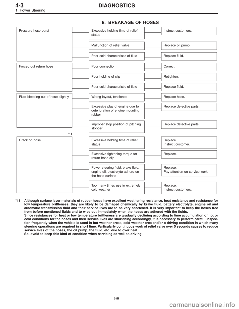
Pressure hose burstExcessive holding time of relief
statusInstruct customers.
Malfunction of relief valveReplace oil pump.
Poor cold characteristic of fluidReplace fluid.
Forced out return hosePoor connectionCorrect.
Poor holding of clipRetighten.
Poor cold characteristic of fluidReplace fluid.
Fluid bleeding out of hose slightlyWrong layout, tensionedReplace hose.
Excessive play of engine due to
deterioration of engine mounting
rubberReplace defective parts.
Improper stop position of pitching
stopperReplace defective parts.
*11
Crack on hose
Excessive holding time of relief
statusReplace.
Instruct customer.
Excessive tightening torque for
return hose clipReplace.
Power steering fluid, brake fluid,
engine oil, electrolyte adhere on
the hose surfaceReplace.
Pay attention on service work.
Too many times use in extremely
cold weatherReplace.
Instruct customers.
*11 Although surface layer materials of rubber hoses have excellent weathering resistance, heat resistance and resistance for
low temperature brittleness, they are likely to be damaged chemically by brake fluid, battery electrolyte, engine oil and
automatic transmission fluid and their service lives are to be very shortened. It is very important to keep the hoses free
from before mentioned fluids and to wipe out immediately when the hoses are adhered with the fluids.
Since resistances for heat or low temperature brittleness are gradually declining according to time accumulation of hot or
cold conditions for the hoses and their service lives are shortening accordingly, it is necessary to perform careful inspec-
tion frequently when the vehicle is used in hot weather areas, cold weather area and/or a driving condition in which many
steering operations are required in short time. Particularly continuous work of relief valve over 5 seconds causes to reduce
service lives of the hoses, the oil pump, the fluid, etc. due to over heat.
So, avoid to keep this kind of condition when servicing as well as driving.
98
4-3DIAGNOSTICS
1. Power Steering
Page 1360 of 3342
15. Hydraulic Unit for ABS System
(ABS 5.3 Type)
B4M0994A
�1Hydraulic control unit
�
2Damper
�
3Stud bolt
�
4Rear-RH outlet
�
5Rear-LH outlet
�
6Secondary inlet
�
7Primary inlet�
8Front-LH outlet
�
9Front-RH outlet
�
10Cable clip
�
11Bracket
�
12Relay box
�
13Motor relay
�
14Valve relay�
15Cap
�
16Connector bracket
Tightening torque: N⋅m (kg-m, ft-lb)
T1: 18±5 (1.8±0.5, 13.0±3.6)
T2: 29±7 (3.0±0.7, 21.7±5.1)
T3: 32±10 (3.3±1.0, 24±7)
A: REMOVAL
1. HYDRAULIC UNIT
1) Disconnect ground cable from battery.
2) Remove air intake duct and canister from engine com-
partment to facilitate removal of hydraulic unit.
3) Disconnect connector from hydraulic unit.
4) Unlock cable clip.
5) Disconnect brake pipes from hydraulic unit.
CAUTION:
Wrap brake pipes with vinyl bag to avoid spilling brake
fluid on vehicle body.
78
4-4SERVICE PROCEDURE
15. Hydraulic Unit for ABS System (ABS 5.3 Type)
Page 1361 of 3342
B4M0996
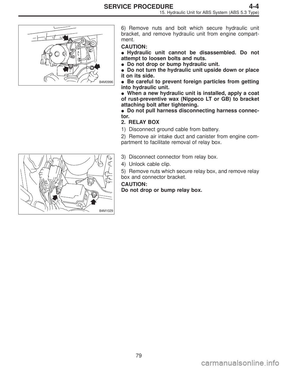
6) Remove nuts and bolt which secure hydraulic unit
bracket, and remove hydraulic unit from engine compart-
ment.
CAUTION:
�Hydraulic unit cannot be disassembled. Do not
attempt to loosen bolts and nuts.
�Do not drop or bump hydraulic unit.
�Do not turn the hydraulic unit upside down or place
it on its side.
�Be careful to prevent foreign particles from getting
into hydraulic unit.
�When a new hydraulic unit is installed, apply a coat
of rust-preventive wax (Nippeco LT or GB) to bracket
attaching bolt after tightening.
�Do not pull harness disconnecting harness connec-
tor.
2. RELAY BOX
1) Disconnect ground cable from battery.
2) Remove air intake duct and canister from engine com-
partment to facilitate removal of relay box.
B4M1029
3) Disconnect connector from relay box.
4) Unlock cable clip.
5) Remove nuts which secure relay box, and remove relay
box and connector bracket.
CAUTION:
Do not drop or bump relay box.
79
4-4SERVICE PROCEDURE
15. Hydraulic Unit for ABS System (ABS 5.3 Type)