Page 1494 of 3342

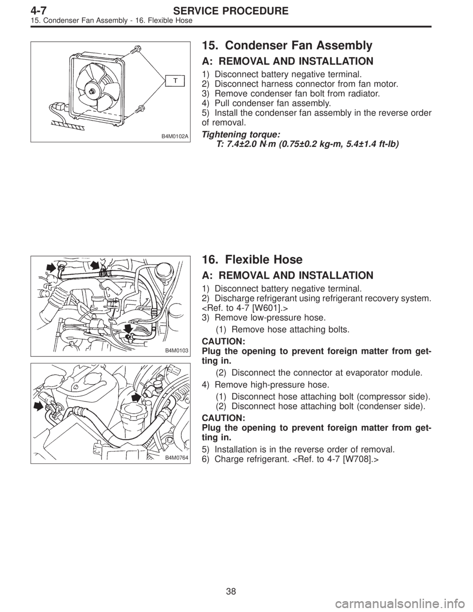
B4M0102A
15. Condenser Fan Assembly
A: REMOVAL AND INSTALLATION
1) Disconnect battery negative terminal.
2) Disconnect harness connector from fan motor.
3) Remove condenser fan bolt from radiator.
4) Pull condenser fan assembly.
5) Install the condenser fan assembly in the reverse order
of removal.
Tightening torque:
T: 7.4±2.0 N⋅m (0.75±0.2 kg-m, 5.4±1.4 ft-lb)
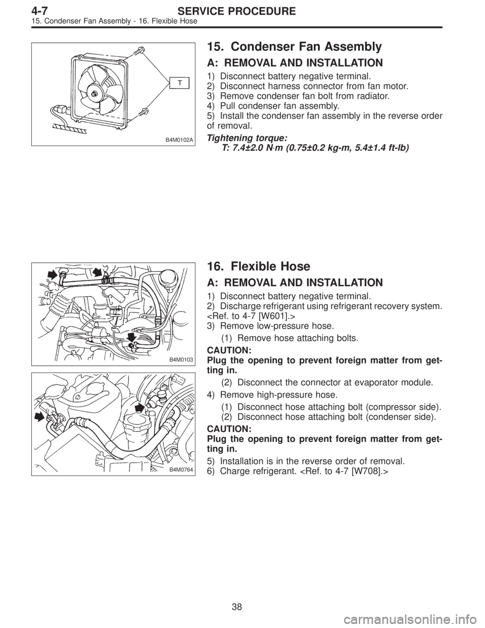
B4M0103
B4M0764
16. Flexible Hose
A: REMOVAL AND INSTALLATION
1) Disconnect battery negative terminal.
2) Discharge refrigerant using refrigerant recovery system.
3) Remove low-pressure hose.
(1) Remove hose attaching bolts.
CAUTION:
Plug the opening to prevent foreign matter from get-
ting in.
(2) Disconnect the connector at evaporator module.
4) Remove high-pressure hose.
(1) Disconnect hose attaching bolt (compressor side).
(2) Disconnect hose attaching bolt (condenser side).
CAUTION:
Plug the opening to prevent foreign matter from get-
ting in.
5) Installation is in the reverse order of removal.
6) Charge refrigerant.
38
4-7SERVICE PROCEDURE
15. Condenser Fan Assembly - 16. Flexible Hose
Page 1495 of 3342

B4M0102A
15. Condenser Fan Assembly
A: REMOVAL AND INSTALLATION
1) Disconnect battery negative terminal.
2) Disconnect harness connector from fan motor.
3) Remove condenser fan bolt from radiator.
4) Pull condenser fan assembly.
5) Install the condenser fan assembly in the reverse order
of removal.
Tightening torque:
T: 7.4±2.0 N⋅m (0.75±0.2 kg-m, 5.4±1.4 ft-lb)
B4M0103
B4M0764
16. Flexible Hose
A: REMOVAL AND INSTALLATION
1) Disconnect battery negative terminal.
2) Discharge refrigerant using refrigerant recovery system.
3) Remove low-pressure hose.
(1) Remove hose attaching bolts.
CAUTION:
Plug the opening to prevent foreign matter from get-
ting in.
(2) Disconnect the connector at evaporator module.
4) Remove high-pressure hose.
(1) Disconnect hose attaching bolt (compressor side).
(2) Disconnect hose attaching bolt (condenser side).
CAUTION:
Plug the opening to prevent foreign matter from get-
ting in.
5) Installation is in the reverse order of removal.
6) Charge refrigerant.
38
4-7SERVICE PROCEDURE
15. Condenser Fan Assembly - 16. Flexible Hose
Page 1547 of 3342
4. Front Bumper
A: REMOVAL
SUPPLEMENTAL RESTRAINT SYSTEM“AIRBAG”
Airbag system wiring harness is routed near the front
bumper assembly.
CAUTION:
�All Airbag system wiring harness and connectors
are colored yellow. Do not use electrical test equip-
ment on these circuits.
�Be careful not to damage Airbag system wiring har-
ness when servicing the front bumper assembly.
B5M0273
1. EXCEPT OUTBACK WITH STEP ROOF
1) Disconnect the ground cable from the battery.
2) Remove two bolts from lower center of bumper.
3) Remove mud guard.
NOTE:
It is not necessary to remove the entire mud guard.
Remove clips from the front section of mud guard, if nec-
essary.
4) Remove the canister.
B5M0274
5) Remove two bolts from side of bumper.
6) Remove front grill.
7) Remove headlight.
B5M0376
8) Remove clips from both sides of front bumper.
NOTE:
When removing, push the pin at the center of clip with a
thin screwdriver.
38
5-1SERVICE PROCEDURE
4. Front Bumper
Page 1548 of 3342
B5M0275
9) Remove bolts (engine compartment side) from bumper
stays.
B5M0276
10) Remove front bumper assembly.
NOTE:
Front bumper surface is accessible for removal after
removing the following parts:
Two bolts (on the lower center of bumper), mud guard,
bolts (on the side of bumper), front grille, headlight, clips
(on both sides of front bumper), clips (on the upper section
of bumper), and clips (on the lower section of bumper).
G6M0095
2. OUTBACK WITH STEP ROOF
1) Disconnect the ground cable from the battery.
B5M0273
2) Remove two bolts from lower center of bumper.
3) Remove mud guard.
NOTE:
It is not necessary to remove the entire mud guard.
Remove clips from the front section of mud guard, if nec-
essary.
4) Remove the canister.
B5M0274
5) Remove two bolts from side of bumper.
6) Remove front grill.
7) Remove headlight.
39
5-1SERVICE PROCEDURE
4. Front Bumper
Page 1560 of 3342
8. Front Fender
A: REMOVAL
SUPPLEMENTAL RESTRAINT SYSTEM“AIRBAG”
Airbag system wiring harness is routed near the front
fender.
CAUTION:
�All Airbag system wiring harness and connectors
are colored yellow. Do not use electrical test equip-
ment on these circuits.
�Be careful not to damage Airbag system wiring har-
ness when servicing the front fender.
B5M0285A
1) Disconnect ground cable from battery.
2) Remove bracket which secures mud guard to front
fender.
3) Remove mud guard.
NOTE:
Do not remove the entire mud guard, only the front section
of it.
4) Remove headlight.
B5M0286
5) Remove bolts which secure front fender.
Remove front fender.
50
5-1SERVICE PROCEDURE
8. Front Fender
Page 1648 of 3342
1. Instrument Panel
Airbag system wiring harness is routed near combination
meter.
CAUTION:
�All Airbag system wiring harness and connectors
are colored yellow. Do not use electrical test equip-
ment on these circuits.
�Be careful not to damage Airbag system wiring har-
ness when servicing the combination meter.
B5M0022A
A: REMOVAL
1) Disconnect GND cable from battery.
2) Remove shift knob (MT model).
3) Remove console cover�
1and front cover�2.
B5M0023
4) Remove console box.
B5M0024A
5) Remove lower cover and then disconnect connector.
B5M0025
6) Remove glove box.
5
5-4SERVICE PROCEDURE
1. Instrument Panel
Page 1654 of 3342
G5M0291
1. Precaution
1) If any of the airbag system parts such as sensors, air-
bag module, airbag control module and harness are dam-
aged or deformed, replace with new genuine parts.
G5M0292
2) When servicing, be sure to turn the ignition switch off,
disconnect the negative (�) battery terminal then the posi-
tive (+) terminal in advance, and wait for more than 20
seconds before starting work.
G5M0293
3) When checking the system, be sure to use a digital cir-
cuit tester. Use of an analog circuit tester may cause the
airbag to activate erroneously. Do not directly apply the
tester probe to any connector terminal of the airbag. When
checking, use a test harness.
G5M0294
4
5-5SERVICE PROCEDURE
1. Precaution
Page 1663 of 3342
A: REMOVAL
1. DRIVER SIDE
1) Set front wheels in straight ahead position.
2) Turn ignition switch off.
3) Disconnect ground cable from battery and wait for at
least 20 seconds before starting work.
H5M0662A
4) Using TORX®BIT T30, remove two TORX®bolts.
H5M0664
5) Disconnect airbag connector on back of airbag module.
6) Refer to“CAUTION”for handling of a removed airbag
module.
2. PASSENGER SIDE
1) Remove instrument panel.
12
5-5SERVICE PROCEDURE
3. Airbag Module