Page 582 of 3342
B2M1179C
4) Installation is in the reverse order of removal.
NOTE:
Before installing operating cylinder, apply grease (SUN-
LIGHT 2: P/N 003602010) to contact point of release lever
and operating cylinder.
Tightening torque:
T1: 18±3 N⋅m (1.8±0.3 kg-m, 13.0±2.2 ft-lb)
T2: 37±3 N⋅m (3.8±0.3 kg-m, 27.5±2.2 ft-lb)
5) After bleeding air from operating cylinder, ensure that
clutch operates properly.
G2M0979
6. Master Cylinder and Reservoir Tank
A: REMOVAL
1) Remove snap pin�2, clevis pin�1and separate push
rod�
3of master cylinder from clutch pedal.
B2M1260A
2) Remove clutch hose from master cylinder.
CAUTION:
Plug up hose connection to prevent clutch fluid from
spilling out.
B2M1261A
3) Remove master cylinder with reservoir tank.
16
2-10SERVICE PROCEDURE
5. Operating Cylinder - 6. Master Cylinder and Reservoir Tank
Page 583 of 3342
G2M0987
B: INSPECTION
If any damage, deformation, wear, swelling, rust or other
faults are found on the cylinder, piston, push rod, fluid
reservoir, seat and gasket, replace the faulty part.
B2M1261A
C: INSTALLATION
1) Install master cylinder to body.
Tightening torque:
18±3 N⋅m (1.8±0.3 kg-m, 13.0±2.2 ft-lb)
B2M1260A
2) Install clutch hose to master cylinder.
CAUTION:
Check that hose is routed properly.
Tightening torque:
18±3 N⋅m (1.8±0.3 kg-m, 13.0±2.2 ft-lb)
B4M1189B
3) Connect push rod�3of master cylinder to clutch pedal,
and install clevis pin�
1and snap pin�2.
NOTE:
Apply grease to clevis pin.
4) After bleeding air from system, ensure that clutch oper-
ates properly.
17
2-10SERVICE PROCEDURE
6. Master Cylinder and Reservoir Tank
Page 584 of 3342
 Remove clutch hoses from clutch damper.
CAUTION:
Cover hose joint to prevent clutch fluid from flowing
out.
2) Remove clutch damper with bracket")
G2M0970
7. Clutch Damper
A: REMOVAL AND INSTALLATION
1) Remove clutch hoses from clutch damper.
CAUTION:
Cover hose joint to prevent clutch fluid from flowing
out.
2) Remove clutch damper with bracket.
G2M0991
3) Installation is in the reverse order of removal.
Tightening torque:
T1: 18±3 N⋅m (1.8±0.3 kg-m, 13.0±2.2 ft-lb)
T2: 25±7 N⋅m (2.5±0.7 kg-m, 18.1±5.1 ft-lb)
4) After bleeding air from system, ensure that clutch oper-
ates properly.
8. Clutch Fluid
A: REPLACEMENT
CAUTION:
�The FMVSS No. 116, fresh DOT3 or 4 brake fluid
must be used.
�Cover bleeder with waste cloth, when loosening it,
to prevent clutch fluid from being splashed over sur-
rounding parts.
�Avoid mixing different brands of clutch fluid to pre-
vent degrading the quality of the fluid.
�Be careful not to allow dirt or dust to get into the
reservoir tank.
NOTE:
�During bleeding operation, keep the clutch reserve tank
filled with clutch fluid to eliminate entry of air.
�Clutch pedal operating must be very slow.
�For convenience and safety, it is advisable to have two
man working.
�The amount of clutch fluid required is approximately 70
m�(2.4 US fl oz, 2.5 Imp fl oz) for total clutch system.
1) Either jack-up vehicle and place a safety stand under it,
or lift-up vehicle.
2) Remove both front and rear wheels.
3) Draw out the clutch fluid from reserve tank with syringe.
4) Refill reservoir tank with recommended clutch fluid.
Recommended clutch fluid:
FMVSS No. 116, fresh DOT3 or 4 brake fluid
5) Bleed air from oil line with the help of a co-worker.
18
2-10SERVICE PROCEDURE
7. Clutch Damper - 8. Clutch Fluid
Page 585 of 3342
 Remove clutch hoses from clutch damper.
CAUTION:
Cover hose joint to prevent clutch fluid from flowing
out.
2) Remove clutch damper with bracket")
G2M0970
7. Clutch Damper
A: REMOVAL AND INSTALLATION
1) Remove clutch hoses from clutch damper.
CAUTION:
Cover hose joint to prevent clutch fluid from flowing
out.
2) Remove clutch damper with bracket.
G2M0991
3) Installation is in the reverse order of removal.
Tightening torque:
T1: 18±3 N⋅m (1.8±0.3 kg-m, 13.0±2.2 ft-lb)
T2: 25±7 N⋅m (2.5±0.7 kg-m, 18.1±5.1 ft-lb)
4) After bleeding air from system, ensure that clutch oper-
ates properly.
8. Clutch Fluid
A: REPLACEMENT
CAUTION:
�The FMVSS No. 116, fresh DOT3 or 4 brake fluid
must be used.
�Cover bleeder with waste cloth, when loosening it,
to prevent clutch fluid from being splashed over sur-
rounding parts.
�Avoid mixing different brands of clutch fluid to pre-
vent degrading the quality of the fluid.
�Be careful not to allow dirt or dust to get into the
reservoir tank.
NOTE:
�During bleeding operation, keep the clutch reserve tank
filled with clutch fluid to eliminate entry of air.
�Clutch pedal operating must be very slow.
�For convenience and safety, it is advisable to have two
man working.
�The amount of clutch fluid required is approximately 70
m�(2.4 US fl oz, 2.5 Imp fl oz) for total clutch system.
1) Either jack-up vehicle and place a safety stand under it,
or lift-up vehicle.
2) Remove both front and rear wheels.
3) Draw out the clutch fluid from reserve tank with syringe.
4) Refill reservoir tank with recommended clutch fluid.
Recommended clutch fluid:
FMVSS No. 116, fresh DOT3 or 4 brake fluid
5) Bleed air from oil line with the help of a co-worker.
18
2-10SERVICE PROCEDURE
7. Clutch Damper - 8. Clutch Fluid
Page 588 of 3342
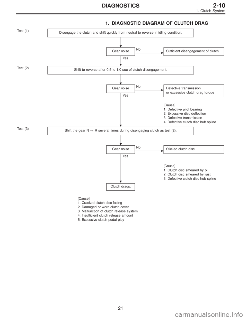
1. DIAGNOSTIC DIAGRAM OF CLUTCH DRAG
Test (1)
Disengage the clutch and shift quickly from neutral to reverse in idling condition.
Gear noise
Ye s
�No
Sufficient disengagement of clutch
Test (2)
Shift to reverse after 0.5 to 1.0 sec of clutch disengagement.
Gear noise
Ye s
�No
Defective transmission
or excessive clutch drag torque
[Cause]
1. Defective pilot bearing
2. Excessive disc deflection
3. Defective transmission
4. Defective clutch disc hub spline
Test (3)
Shift the gear N,R several times during disengaging clutch as test (2).
Gear noise
Ye s
�No
Sticked clutch disc
[Cause]
1. Clutch disc smeared by oil
2. Clutch disc smeared by rust
3. Defective clutch disc hub spline
Clutch drags.
[Cause]
1. Cracked clutch disc facing
2. Damaged or worn clutch cover
3. Malfunction of clutch release system
4. Insufficient clutch release amount
5. Excessive clutch pedal play
�
�
�
�
�
�
21
2-10DIAGNOSTICS
1. Clutch System
Page 590 of 3342
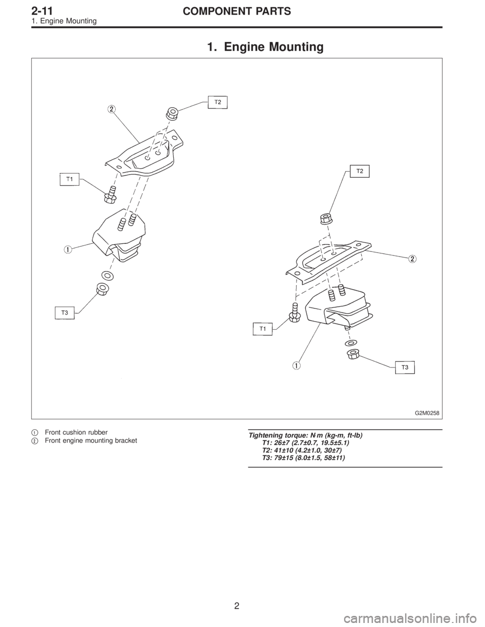
1. Engine Mounting
G2M0258
�1Front cushion rubber
�
2Front engine mounting bracketTightening torque: N⋅m (kg-m, ft-lb)
T1: 26±7 (2.7±0.7, 19.5±5.1)
T2: 41±10 (4.2±1.0, 30±7)
T3: 79±15 (8.0±1.5, 58±11)
2
2-11COMPONENT PARTS
1. Engine Mounting
Page 591 of 3342
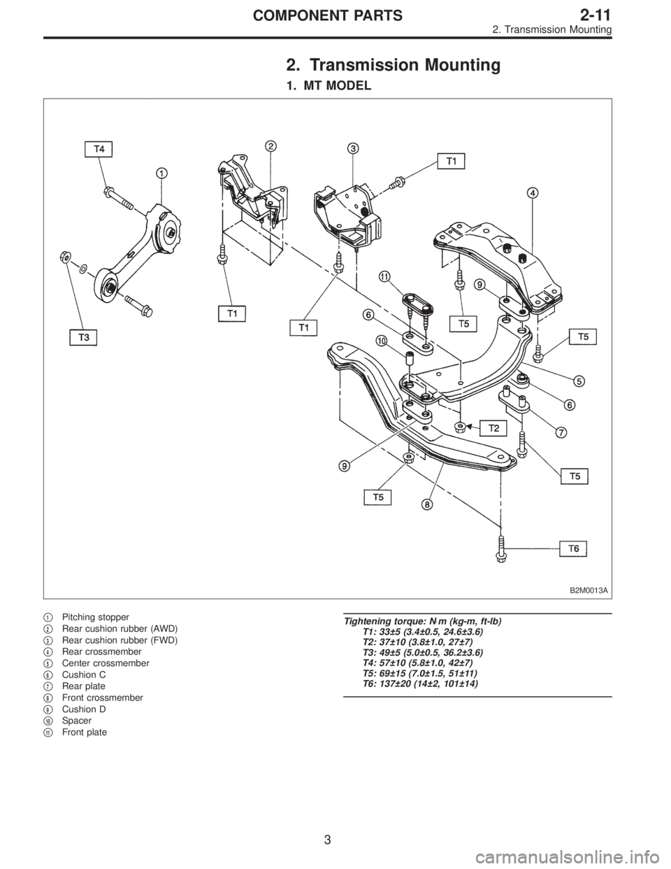
2. Transmission Mounting
1. MT MODEL
B2M0013A
�1Pitching stopper
�
2Rear cushion rubber (AWD)
�
3Rear cushion rubber (FWD)
�
4Rear crossmember
�
5Center crossmember
�
6Cushion C
�
7Rear plate
�
8Front crossmember
�
9Cushion D
�
10Spacer
�
11Front plate
Tightening torque: N⋅m (kg-m, ft-lb)
T1: 33±5 (3.4±0.5, 24.6±3.6)
T2: 37±10 (3.8±1.0, 27±7)
T3: 49±5 (5.0±0.5, 36.2±3.6)
T4: 57±10 (5.8±1.0, 42±7)
T5: 69±15 (7.0±1.5, 51±11)
T6: 137±20 (14±2, 101±14)
3
2-11COMPONENT PARTS
2. Transmission Mounting
Page 592 of 3342
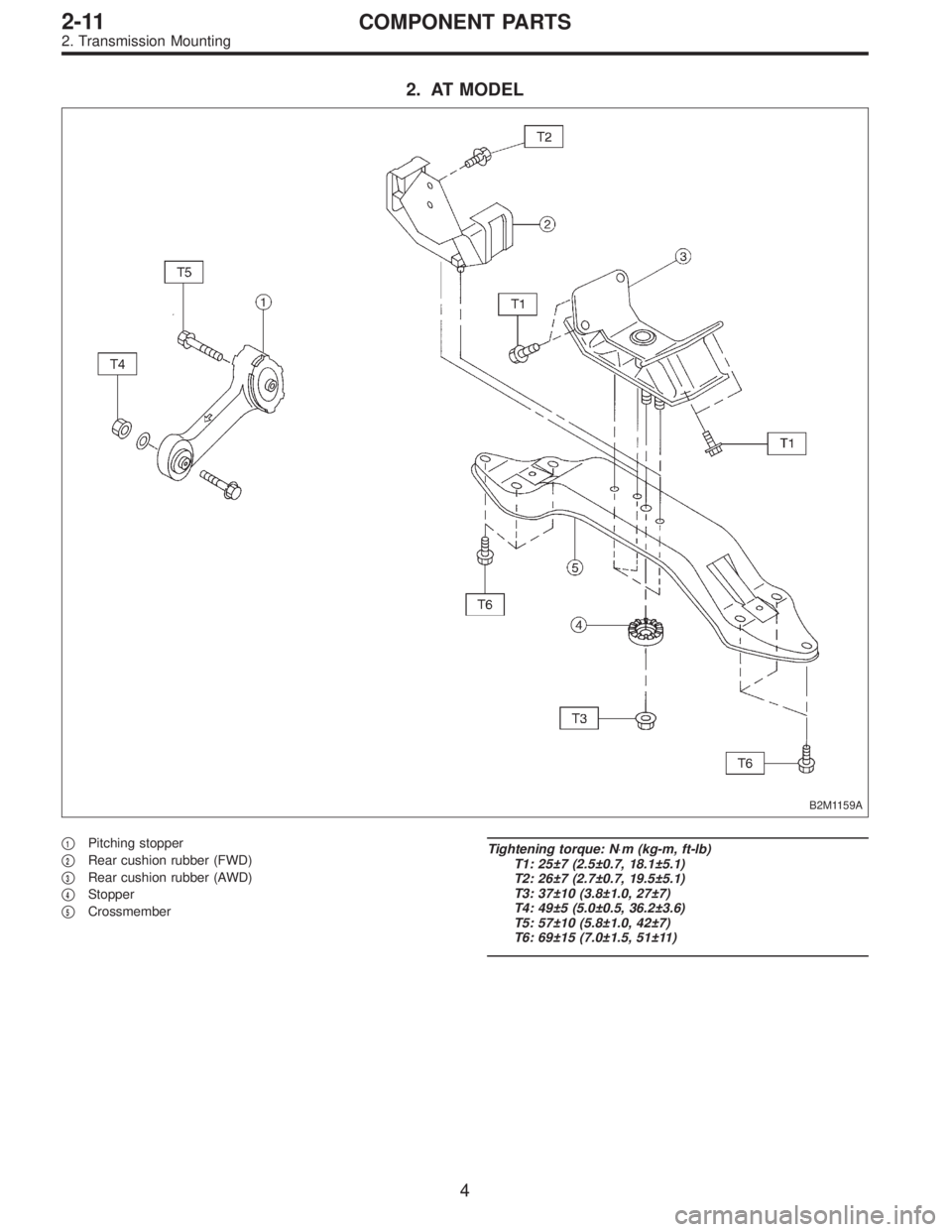
2. AT MODEL
B2M1159A
�1Pitching stopper
�
2Rear cushion rubber (FWD)
�
3Rear cushion rubber (AWD)
�
4Stopper
�
5Crossmember
Tightening torque: N⋅m (kg-m, ft-lb)
T1: 25±7 (2.5±0.7, 18.1±5.1)
T2: 26±7 (2.7±0.7, 19.5±5.1)
T3: 37±10 (3.8±1.0, 27±7)
T4: 49±5 (5.0±0.5, 36.2±3.6)
T5: 57±10 (5.8±1.0, 42±7)
T6: 69±15 (7.0±1.5, 51±11)
4
2-11COMPONENT PARTS
2. Transmission Mounting
 Installation is in the reverse order of removal.
NOTE:
Before installing operating cylinder, apply grease (SUN-
LIGHT 2: P/N 003602010) to contact point of release lever
and operating cyli")