Page 565 of 3342
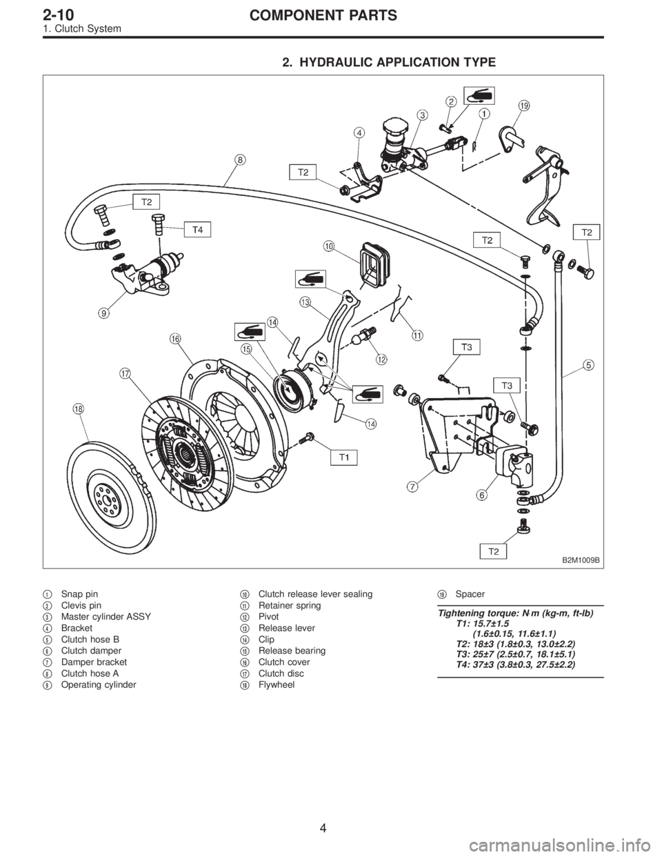
2. HYDRAULIC APPLICATION TYPE
B2M1009B
�1Snap pin
�
2Clevis pin
�
3Master cylinder ASSY
�
4Bracket
�
5Clutch hose B
�
6Clutch damper
�
7Damper bracket
�
8Clutch hose A
�
9Operating cylinder�
10Clutch release lever sealing
�
11Retainer spring
�
12Pivot
�
13Release lever
�
14Clip
�
15Release bearing
�
16Clutch cover
�
17Clutch disc
�
18Flywheel�
19Spacer
Tightening torque: N⋅m (kg-m, ft-lb)
T1: 15.7±1.5
(1.6±0.15, 11.6±1.1)
T2: 18±3 (1.8±0.3, 13.0±2.2)
T3: 25±7 (2.5±0.7, 18.1±5.1)
T4: 37±3 (3.8±0.3, 27.5±2.2)
4
2-10COMPONENT PARTS
1. Clutch System
Page 570 of 3342
G2M0972
4) Tighten air bleeder.
Tightening torque:
T: 18±3 N⋅m (1.8±0.3 kg-m, 13.0±2.2 ft-lb)
B2M1178A
5) Remove air chamber.
6) Repeat steps 1) through 3) using air bleeder on oper-
ating cylinder.
B2M1179A
7) Tighten air bleeder.
Tightening torque:
T: 18±3 N⋅m (1.8±0.3 kg-m, 13.0±2.2 ft-lb)
8) After depressing the clutch pedal, make sure that there
are no leaks evident in the entire system.
9) After bleeding air from system, ensure that clutch oper-
ates properly.
B2M0633A
3. Release Bearing and Lever
A: REMOVAL
1. MECHANICAL APPLICATION TYPE
1) Remove release lever return spring�
1(Models without
hill holder only).
2) Remove the two clips�
2from clutch release lever�3
and remove release bearing�6.
CAUTION:
Be careful not to deform clips.
3) Remove release lever seal�
4.
8
2-10SERVICE PROCEDURE
2. On-Car Service - 3. Release Bearing and Lever
Page 571 of 3342
G2M0972
4) Tighten air bleeder.
Tightening torque:
T: 18±3 N⋅m (1.8±0.3 kg-m, 13.0±2.2 ft-lb)
B2M1178A
5) Remove air chamber.
6) Repeat steps 1) through 3) using air bleeder on oper-
ating cylinder.
B2M1179A
7) Tighten air bleeder.
Tightening torque:
T: 18±3 N⋅m (1.8±0.3 kg-m, 13.0±2.2 ft-lb)
8) After depressing the clutch pedal, make sure that there
are no leaks evident in the entire system.
9) After bleeding air from system, ensure that clutch oper-
ates properly.
B2M0633A
3. Release Bearing and Lever
A: REMOVAL
1. MECHANICAL APPLICATION TYPE
1) Remove release lever return spring�
1(Models without
hill holder only).
2) Remove the two clips�
2from clutch release lever�3
and remove release bearing�6.
CAUTION:
Be careful not to deform clips.
3) Remove release lever seal�
4.
8
2-10SERVICE PROCEDURE
2. On-Car Service - 3. Release Bearing and Lever
Page 574 of 3342
 While pushing release lever�
3to pivot and twisting it to
both sides, fit retainer spring�
5onto the constricted portion
of pivot.
NOTE:
Confirm that retaine")
B2M0633A
1. MECHANICAL APPLICATION TYPE
1) While pushing release lever�
3to pivot and twisting it to
both sides, fit retainer spring�
5onto the constricted portion
of pivot.
NOTE:
Confirm that retainer spring is securely fitted by observing
it through the main case hole.
2) Install release bearing�
6and fasten it with two clips�2.
3) Install release lever seal�
4.
G2M0235
4) After remounting engine and transmission on body,
make adjustment of the clutch release lever end play.
CAUTION:
Take care not to twist the cable during adjustment.
5) Install release lever return spring (Models without hill
holder only).
NOTE:
Hook up the return spring to right side hole of the release
lever.
B2M1257C
2. HYDRAULIC APPLICATION TYPE
1) While pushing release lever�
1to pivot and twisting it to
both sides, fit retainer spring�
2onto the constricted portion
of pivot.
NOTE:
�Apply grease (SUNLIGHT 2: P/N 003602010) to contact
point of release lever and operating cylinder.
�Confirm that retainer spring is securely fitted by observ-
ing it through the main case hole.
2) Install release bearing�
3and fasten it with two clips�4.
3) Install release lever seal�
5.
4) Install operating cylinder�
6.
Tightening torque:
T: 37±3 N⋅m (3.8±0.3 kg-m, 27.5±2.2 ft-lb)
11
2-10SERVICE PROCEDURE
3. Release Bearing and Lever
Page 578 of 3342
 Damage of facing and ring gear
If defective, replace")
G2M0250
3. FLYWHEEL
CAUTION:
Since this bearing is grease sealed and is of a nonlu-
brication type, do not wash with gasoline or any sol-
vent.
1) Damage of facing and ring gear
If defective, replace flywheel.
G2M0251
2) Smoothness of rotation
Rotate ball bearing applying pressure in thrust direction.
If noise or excessive play is noted, replace ball bearing as
follows:
(1) Drive out ball bearing from flywheel.
(2) Press bearing into flywheel until bearing end sur-
face is flush with clutch disc contact surface of flywheel.
Do not press inner race.
ST 899754112 SNAP RING PRESS
B2M0331A
B2M0332A
C: INSTALLATION
1) Install flywheel.
2) Install ST, and tighten the flywheel attaching bolts to the
specified torque.
ST 498497100 CRANKSHAFT STOPPER
Tightening torque:
72±3 N⋅m (7.3±0.3 kg-m, 52.8±2.2 ft-lb)
NOTE:
Tighten flywheel installing bolts gradually. Each bolt should
be tightened to the specified torque in a crisscross fashion.
G2M0253
3) Insert ST into the clutch disc and install them on the
flywheel by inserting the ST end into the pilot bearing.
ST 499747100 CLUTCH DISC GUIDE
14
2-10SERVICE PROCEDURE
4. Clutch Disc and Cover
Page 579 of 3342
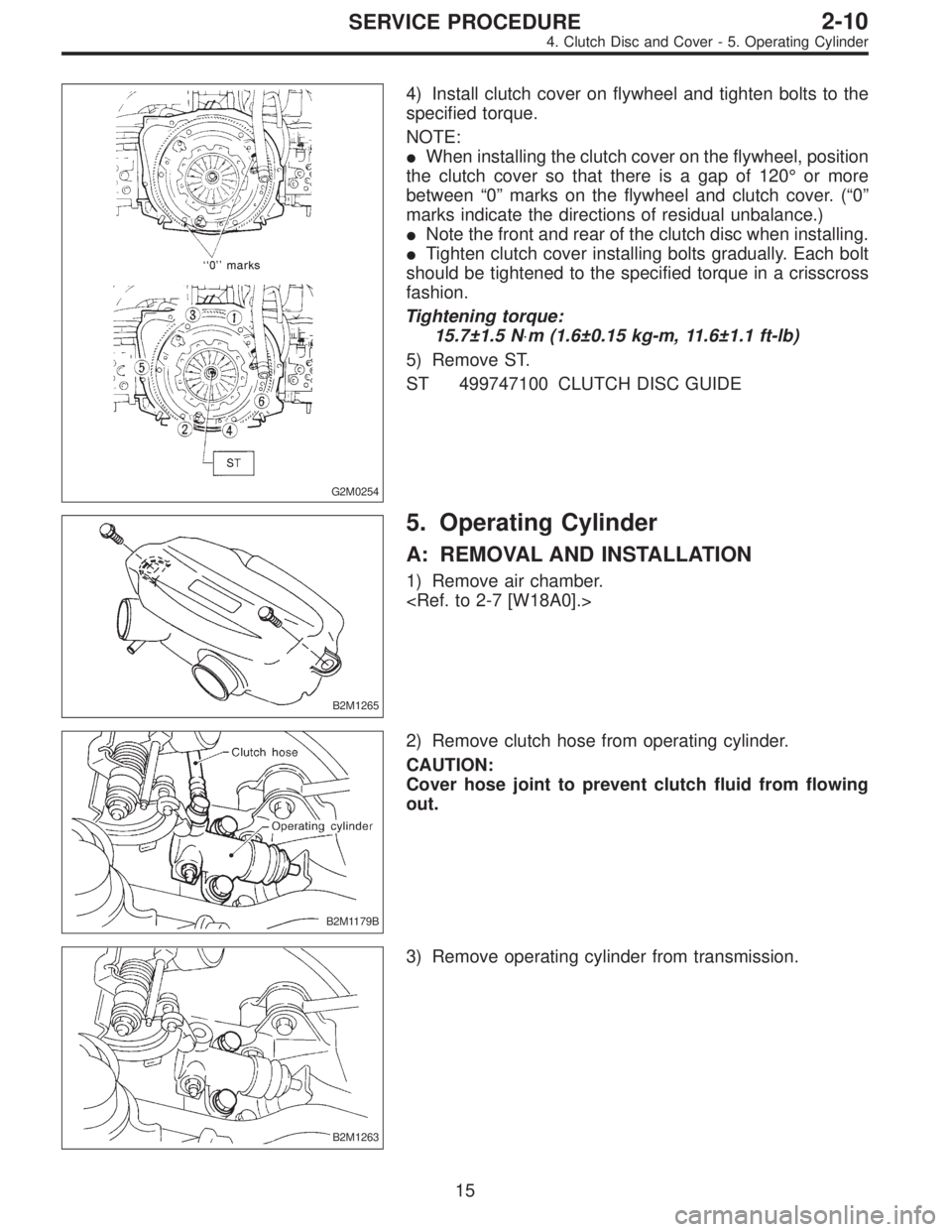
G2M0254
4) Install clutch cover on flywheel and tighten bolts to the
specified torque.
NOTE:
�When installing the clutch cover on the flywheel, position
the clutch cover so that there is a gap of 120°or more
between“0”marks on the flywheel and clutch cover. (“0”
marks indicate the directions of residual unbalance.)
�Note the front and rear of the clutch disc when installing.
�Tighten clutch cover installing bolts gradually. Each bolt
should be tightened to the specified torque in a crisscross
fashion.
Tightening torque:
15.7±1.5 N⋅m (1.6±0.15 kg-m, 11.6±1.1 ft-lb)
5) Remove ST.
ST 499747100 CLUTCH DISC GUIDE
B2M1265
5. Operating Cylinder
A: REMOVAL AND INSTALLATION
1) Remove air chamber.
B2M1179B
2) Remove clutch hose from operating cylinder.
CAUTION:
Cover hose joint to prevent clutch fluid from flowing
out.
B2M1263
3) Remove operating cylinder from transmission.
15
2-10SERVICE PROCEDURE
4. Clutch Disc and Cover - 5. Operating Cylinder
Page 580 of 3342
G2M0254
4) Install clutch cover on flywheel and tighten bolts to the
specified torque.
NOTE:
�When installing the clutch cover on the flywheel, position
the clutch cover so that there is a gap of 120°or more
between“0”marks on the flywheel and clutch cover. (“0”
marks indicate the directions of residual unbalance.)
�Note the front and rear of the clutch disc when installing.
�Tighten clutch cover installing bolts gradually. Each bolt
should be tightened to the specified torque in a crisscross
fashion.
Tightening torque:
15.7±1.5 N⋅m (1.6±0.15 kg-m, 11.6±1.1 ft-lb)
5) Remove ST.
ST 499747100 CLUTCH DISC GUIDE
B2M1265
5. Operating Cylinder
A: REMOVAL AND INSTALLATION
1) Remove air chamber.
B2M1179B
2) Remove clutch hose from operating cylinder.
CAUTION:
Cover hose joint to prevent clutch fluid from flowing
out.
B2M1263
3) Remove operating cylinder from transmission.
15
2-10SERVICE PROCEDURE
4. Clutch Disc and Cover - 5. Operating Cylinder
Page 581 of 3342
B2M1179C
4) Installation is in the reverse order of removal.
NOTE:
Before installing operating cylinder, apply grease (SUN-
LIGHT 2: P/N 003602010) to contact point of release lever
and operating cylinder.
Tightening torque:
T1: 18±3 N⋅m (1.8±0.3 kg-m, 13.0±2.2 ft-lb)
T2: 37±3 N⋅m (3.8±0.3 kg-m, 27.5±2.2 ft-lb)
5) After bleeding air from operating cylinder, ensure that
clutch operates properly.
G2M0979
6. Master Cylinder and Reservoir Tank
A: REMOVAL
1) Remove snap pin�2, clevis pin�1and separate push
rod�
3of master cylinder from clutch pedal.
B2M1260A
2) Remove clutch hose from master cylinder.
CAUTION:
Plug up hose connection to prevent clutch fluid from
spilling out.
B2M1261A
3) Remove master cylinder with reservoir tank.
16
2-10SERVICE PROCEDURE
5. Operating Cylinder - 6. Master Cylinder and Reservoir Tank
![SUBARU LEGACY 1997 Service Repair Manual G2M0972
4) Tighten air bleeder.
Tightening torque:
T: 18±3 N⋅m (1.8±0.3 kg-m, 13.0±2.2 ft-lb)
B2M1178A
5) Remove air chamber.
<Ref. to 2-7 [W18A0].>
6) Repeat steps 1) through 3) using air bleede](/manual-img/17/57434/w960_57434-569.png "SUBARU LEGACY 1997 Service Repair Manual G2M0972
4) Tighten air bleeder.
Tightening torque:
T: 18±3 N⋅m (1.8±0.3 kg-m, 13.0±2.2 ft-lb)
B2M1178A
5) Remove air chamber.
<Ref. to 2-7 [W18A0].>
6) Repeat steps 1) through 3) using air bleede")
![SUBARU LEGACY 1997 Service Repair Manual G2M0972
4) Tighten air bleeder.
Tightening torque:
T: 18±3 N⋅m (1.8±0.3 kg-m, 13.0±2.2 ft-lb)
B2M1178A
5) Remove air chamber.
<Ref. to 2-7 [W18A0].>
6) Repeat steps 1) through 3) using air bleede](/manual-img/17/57434/w960_57434-570.png "SUBARU LEGACY 1997 Service Repair Manual G2M0972
4) Tighten air bleeder.
Tightening torque:
T: 18±3 N⋅m (1.8±0.3 kg-m, 13.0±2.2 ft-lb)
B2M1178A
5) Remove air chamber.
<Ref. to 2-7 [W18A0].>
6) Repeat steps 1) through 3) using air bleede")

 Installation is in the reverse order of removal.
NOTE:
Before installing operating cylinder, apply grease (SUN-
LIGHT 2: P/N 003602010) to contact point of release lever
and operating cyli")