Page 519 of 3342
B2M1682A
B: INSTALLATION
1. 2200 cc MODEL
1) Install knock sensor to cylinder block.
Tightening torque:
23.5±2.9 N⋅m (2.4±0.3 kg-m, 17.3±2.1 ft-lb)
NOTE:
The extraction area of the knock sensor cord must be posi-
tioned at a 45°angle relative to the engine rear.
B2M1681
2) Connect knock sensor connector.
B2M1687A
NOTE:
The knock sensor cord must pass between the engine
harness and engine coolant hose.
B2M1680A
3) Fasten engine harness to engine coolant hose with
band clip.
NOTE:
Make sure that the throttle linkage does not interfere with
other parts in the operating area.
B2M1679
4) Install air intake chamber.
37
2-7SERVICE PROCEDURE
19. Knock Sensor
Page 520 of 3342
G6M0095
5) Connect battery ground cable to battery ground termi-
nal.
B2M1682A
2. 2500 cc MODEL
1) Install knock sensor to cylinder block.
Tightening torque:
23.5±2.9 N⋅m (2.4±0.3 kg-m, 17.3±2.1 ft-lb)
NOTE:
The extraction area of the knock sensor cord must be posi-
tioned at a 45°angle relative to the engine rear.
B2M1686
2) Connect knock sensor connector.
B2M1688A
NOTE:
The connector must be connected to the engine front end
of the engine coolant hose.
B2M1689A
38
2-7SERVICE PROCEDURE
19. Knock Sensor
Page 521 of 3342
B2M1685A
3) Fasten engine harness to engine coolant hose with
band clip.
NOTE:
Make sure that the throttle linkage does not interfere with
other parts in the operating area.
B2M1179E
4) Install operating cylinder. (MT vehicle only)
Tightening torque:
37±3 N⋅m (3.8±0.3 kg-m, 27.3±2.2 ft-lb)
NOTE:
Apply grease to contact point of release lever and operat-
ing cylinder rod.
B2M1683
5) Install air intake chamber.
G6M0095
6) Connect battery ground cable to battery ground termi-
nal.
39
2-7SERVICE PROCEDURE
19. Knock Sensor
Page 523 of 3342
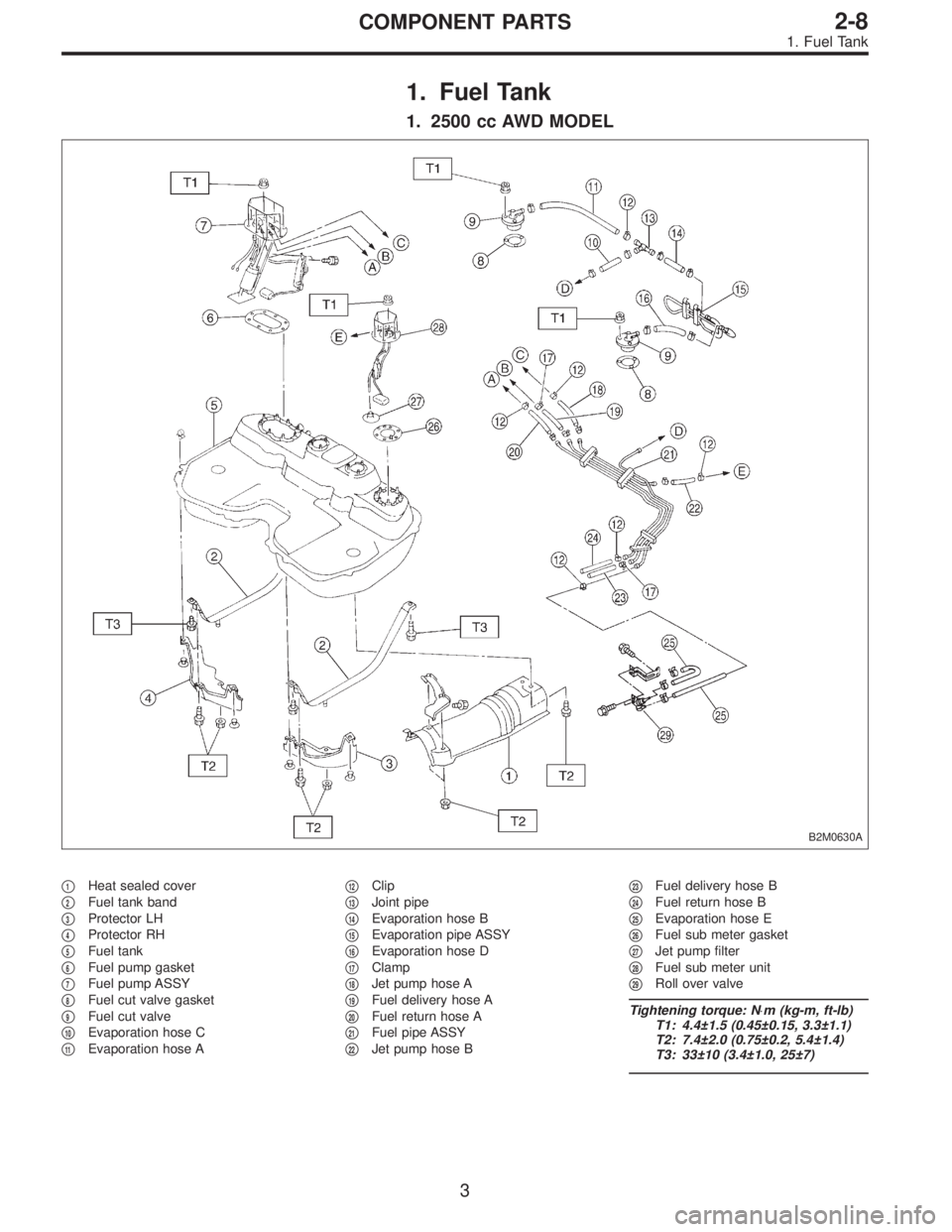
1. Fuel Tank
1. 2500 cc AWD MODEL
B2M0630A
�1Heat sealed cover
�
2Fuel tank band
�
3Protector LH
�
4Protector RH
�
5Fuel tank
�
6Fuel pump gasket
�
7Fuel pump ASSY
�
8Fuel cut valve gasket
�
9Fuel cut valve
�
10Evaporation hose C
�
11Evaporation hose A�
12Clip
�
13Joint pipe
�
14Evaporation hose B
�
15Evaporation pipe ASSY
�
16Evaporation hose D
�
17Clamp
�
18Jet pump hose A
�
19Fuel delivery hose A
�
20Fuel return hose A
�
21Fuel pipe ASSY
�
22Jet pump hose B�
23Fuel delivery hose B
�
24Fuel return hose B
�
25Evaporation hose E
�
26Fuel sub meter gasket
�
27Jet pump filter
�
28Fuel sub meter unit
�
29Roll over valve
Tightening torque: N⋅m (kg-m, ft-lb)
T1: 4.4±1.5 (0.45±0.15, 3.3±1.1)
T2: 7.4±2.0 (0.75±0.2, 5.4±1.4)
T3: 33±10 (3.4±1.0, 25±7)
3
2-8COMPONENT PARTS
1. Fuel Tank
Page 524 of 3342
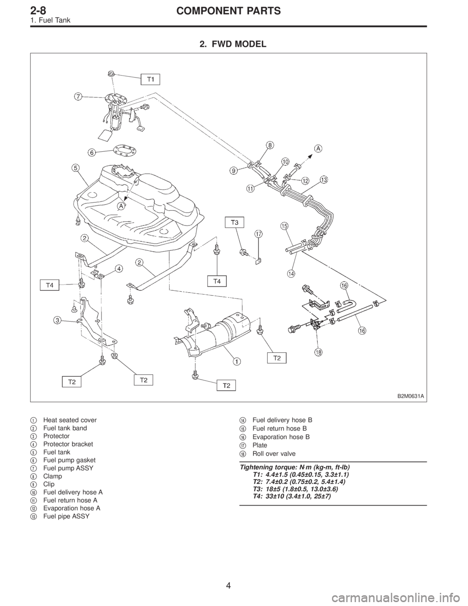
2. FWD MODEL
B2M0631A
�1Heat seated cover
�
2Fuel tank band
�
3Protector
�
4Protector bracket
�
5Fuel tank
�
6Fuel pump gasket
�
7Fuel pump ASSY
�
8Clamp
�
9Clip
�
10Fuel delivery hose A
�
11Fuel return hose A
�
12Evaporation hose A
�
13Fuel pipe ASSY�
14Fuel delivery hose B
�
15Fuel return hose B
�
16Evaporation hose B
�
17Plate
�
18Roll over valve
Tightening torque: N⋅m (kg-m, ft-lb)
T1: 4.4±1.5 (0.45±0.15, 3.3±1.1)
T2: 7.4±0.2 (0.75±0.2, 5.4±1.4)
T3: 18±5 (1.8±0.5, 13.0±3.6)
T4: 33±10 (3.4±1.0, 25±7)
4
2-8COMPONENT PARTS
1. Fuel Tank
Page 526 of 3342
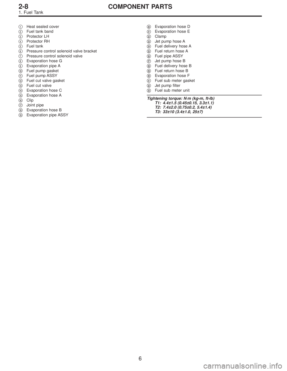
�1Heat sealed cover
�
2Fuel tank band
�
3Protector LH
�
4Protector RH
�
5Fuel tank
�
6Pressure control solenoid valve bracket
�
7Pressure control solenoid valve
�
8Evaporation hose G
�
9Evaporation pipe A
�
10Fuel pump gasket
�
11Fuel pump ASSY
�
12Fuel cut valve gasket
�
13Fuel cut valve
�
14Evaporation hose C
�
15Evaporation hose A
�
16Clip
�
17Joint pipe
�
18Evaporation hose B
�
19Evaporation pipe ASSY�
20Evaporation hose D
�
21Evaporation hose E
�
22Clamp
�
23Jet pump hose A
�
24Fuel delivery hose A
�
25Fuel return hose A
�
26Fuel pipe ASSY
�
27Jet pump hose B
�
28Fuel delivery hose B
�
29Fuel return hose B
�
30Evaporation hose F
�
31Fuel sub meter gasket
�
32Jet pump filter
�
33Fuel sub meter unit
Tightening torque: N⋅m (kg-m, ft-lb)
T1: 4.4±1.5 (0.45±0.15, 3.3±1.1)
T2: 7.4±2.0 (0.75±0.2, 5.4±1.4)
T3: 33±10 (3.4±1.0, 25±7)
6
2-8COMPONENT PARTS
1. Fuel Tank
Page 529 of 3342

�1Clamp
�
2Fuel delivery hose A
�
3Fuel filter bracket
�
4Fuel filter holder
�
5Fuel filter cup
�
6Fuel filter
�
7Evaporation hose
�
8Clip
�
9Fuel delivery hose B
�
10Fuel return hose
�
11Roll over valve
�
12Roll over valve bracket
�
13Evaporation hose H
�
14Evaporation hose I
�
15Evaporation pipe B
�
16Canister hose A
�
17Canister hose B
�
18Canister holder
�
19Canister upper bracket
�
20Cushion rubber
�
21Canister lower bracket
�
22Canister
�
23Fuel pipe ASSY
�
24Fuel filler valve
�
25Fuel filler pipe
�
26Packing�
27Ring A
�
28Ring B
�
29Fuel filler cap
�
30Fuel filler pipe protector
�
31Fuel tank pressure sensor
�
32Fuel tank pressure sensor hose A
�
33Fuel tank pressure sensor bracket
�
34Grommet
�
35Fuel tank pressure sensor hose B
�
36Air ventilator hose A
�
37Air ventilator pipe A
�
38Air ventilator hose B
�
39Air ventilator pipe B
�
40Air ventilator pipe protector
�
41Vent control solenoid valve
�
42Vent control solenoid valve hose
�
43Air filter hose A
�
44Air filter hose B
�
45Air filter
�
46Tapping screw
Tightening torque: N⋅m (kg-m, ft-lb)
T1: 23±7 (2.3±0.7, 17±5.1)
T2: 25±7 (2.5±0.7, 18±5.1)
9
2-8COMPONENT PARTS
2. Fuel Line
Page 531 of 3342
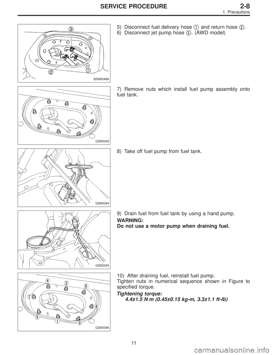
B2M0048A
5) Disconnect fuel delivery hose�1and return hose�2.
6) Disconnect jet pump hose�
3. (AWD model)
G2M0343
7) Remove nuts which install fuel pump assembly onto
fuel tank.
G2M0344
8) Take off fuel pump from fuel tank.
G2M0345
9) Drain fuel from fuel tank by using a hand pump.
WARNING:
Do not use a motor pump when draining fuel.
G2M0346
10) After draining fuel, reinstall fuel pump.
Tighten nuts in numerical sequence shown in Figure to
specified torque.
Tightening torque:
4.4±1.5 N⋅m (0.45±0.15 kg-m, 3.3±1.1 ft-lb)
11
2-8SERVICE PROCEDURE
1. Precautions
 Install knock sensor to cylinder block.
Tightening torque:
23.5±2.9 N⋅m (2.4±0.3 kg-m, 17.3±2.1 ft-lb)
NOTE:
The extraction area of the knock sensor c")
 Connect battery ground cable to battery ground termi-
nal.
B2M1682A
2. 2500 cc MODEL
1) Install knock sensor to cylinder block.
Tightening torque:
23.5±2.9 N⋅m (2.4±0.3 kg-m, 17.3±2.1")
 Fasten engine harness to engine coolant hose with
band clip.
NOTE:
Make sure that the throttle linkage does not interfere with
other parts in the operating area.
B2M1179E
4) Install operat")