Page 503 of 3342
 When using Subaru Select Monitor;
(1) Connect Subaru Select Monitor to the data link con-
nector.
(2) Turn ignition switch to ON and SSM switch to ON.
(3) Select mode “F10”.
(4) Adjust")
G2M0096
4) When using Subaru Select Monitor;
(1) Connect Subaru Select Monitor to the data link con-
nector.
(2) Turn ignition switch to ON and SSM switch to ON.
(3) Select mode “F10”.
(4) Adjust throttle position sensor to specified data.
Condition / Specified data.
Throttle fully closed / 0.50 V
(5) Tighten throttle position sensor holding screws.
G2M0416
10. Camshaft Position Sensor
A: REMOVAL AND INSTALLATION
1) Disconnect connector from camshaft position sensor.
G2M0417
2) Remove camshaft position sensor from camshaft sup-
port LH.
3) Installation is in the reverse order of removal.
Tightening torque:
6.4±0.5 N⋅m (0.65±0.05 kg-m, 4.7±0.4 ft-lb)
B2M0355
11. Pressure Sensor (AT model)
A: REMOVAL AND INSTALLATION
1) Disconnect connector from pressure sensor.
2) Disconnect hose from pressure sensor.
B2M0356
3) Remove pressure sensor from bracket.
4) Installation is in the reverse order of removal.
Tightening torque:
6.4±0.5 N⋅m (0.65±0.05 kg-m, 4.7±0.4 ft-lb)
28
2-7SERVICE PROCEDURE
9. Throttle Position Sensor - 11. Pressure Sensor (AT model)
Page 504 of 3342
B2M0164
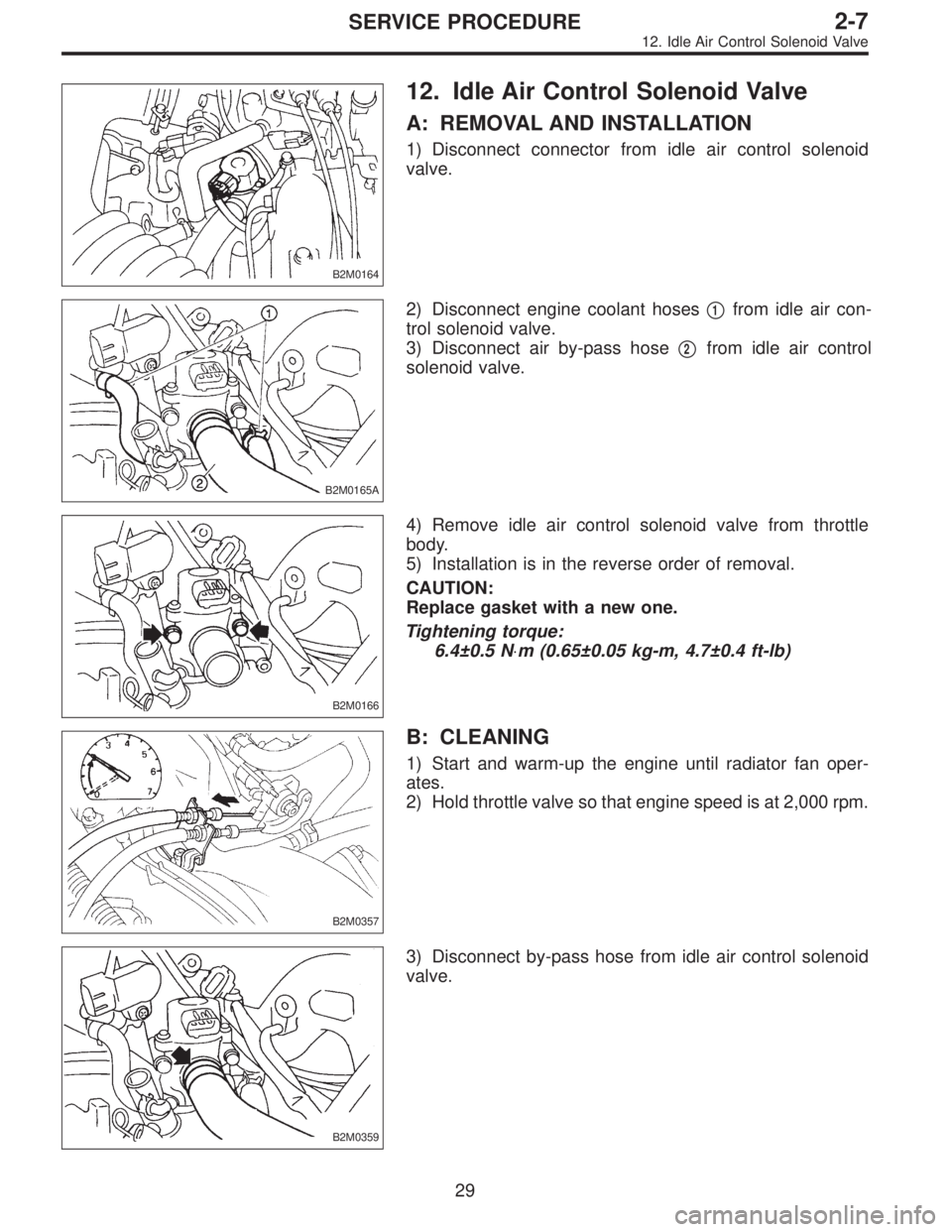
12. Idle Air Control Solenoid Valve
A: REMOVAL AND INSTALLATION
1) Disconnect connector from idle air control solenoid
valve.
B2M0165A
2) Disconnect engine coolant hoses�1from idle air con-
trol solenoid valve.
3) Disconnect air by-pass hose�
2from idle air control
solenoid valve.
B2M0166
4) Remove idle air control solenoid valve from throttle
body.
5) Installation is in the reverse order of removal.
CAUTION:
Replace gasket with a new one.
Tightening torque:
6.4±0.5 N⋅m (0.65±0.05 kg-m, 4.7±0.4 ft-lb)
B2M0357
B: CLEANING
1) Start and warm-up the engine until radiator fan oper-
ates.
2) Hold throttle valve so that engine speed is at 2,000 rpm.
B2M0359
3) Disconnect by-pass hose from idle air control solenoid
valve.
29
2-7SERVICE PROCEDURE
12. Idle Air Control Solenoid Valve
Page 507 of 3342
B2M0362
3) Remove pressure sources switching solenoid valve
from bracket.
4) Installation is in the reverse order of removal.
Tightening torque:
6.4±0.5 N⋅m (0.65±0.05 kg-m, 4.7±0.4 ft-lb)
G2M0398
14. Fuel Injector
A: REMOVAL AND INSTALLATION
1) Release fuel pressure.
2) Disconnect connector from fuel injector.
G2M0431
3) Remove fuel injector from fuel pipe assembly.
B2M0169A
4) Installation is in the reverse order of removal.
CAUTION:
Replace O-rings and insulator.
Tightening torque:
T: 3.4±0.5 N⋅m (0.35±0.05 kg-m, 2.5±0.4 ft-lb)
�
1O-ring B
�
2O-ring A
�
3Fuel injector
�
4Insulator
�
5Fuel injector cup
G6M0095
15. Engine Control Module
A: REMOVAL AND INSTALLATION
1) Disconnect battery ground cable.
31
2-7SERVICE PROCEDURE
13. Pressure Sources Switching Solenoid Valve (AT model) - 15. Engine Control Module
Page 508 of 3342
B2M0362
3) Remove pressure sources switching solenoid valve
from bracket.
4) Installation is in the reverse order of removal.
Tightening torque:
6.4±0.5 N⋅m (0.65±0.05 kg-m, 4.7±0.4 ft-lb)
G2M0398
14. Fuel Injector
A: REMOVAL AND INSTALLATION
1) Release fuel pressure.
2) Disconnect connector from fuel injector.
G2M0431
3) Remove fuel injector from fuel pipe assembly.
B2M0169A
4) Installation is in the reverse order of removal.
CAUTION:
Replace O-rings and insulator.
Tightening torque:
T: 3.4±0.5 N⋅m (0.35±0.05 kg-m, 2.5±0.4 ft-lb)
�
1O-ring B
�
2O-ring A
�
3Fuel injector
�
4Insulator
�
5Fuel injector cup
G6M0095
15. Engine Control Module
A: REMOVAL AND INSTALLATION
1) Disconnect battery ground cable.
31
2-7SERVICE PROCEDURE
13. Pressure Sources Switching Solenoid Valve (AT model) - 15. Engine Control Module
Page 509 of 3342
B2M0362
3) Remove pressure sources switching solenoid valve
from bracket.
4) Installation is in the reverse order of removal.
Tightening torque:
6.4±0.5 N⋅m (0.65±0.05 kg-m, 4.7±0.4 ft-lb)
G2M0398
14. Fuel Injector
A: REMOVAL AND INSTALLATION
1) Release fuel pressure.
2) Disconnect connector from fuel injector.
G2M0431
3) Remove fuel injector from fuel pipe assembly.
B2M0169A
4) Installation is in the reverse order of removal.
CAUTION:
Replace O-rings and insulator.
Tightening torque:
T: 3.4±0.5 N⋅m (0.35±0.05 kg-m, 2.5±0.4 ft-lb)
�
1O-ring B
�
2O-ring A
�
3Fuel injector
�
4Insulator
�
5Fuel injector cup
G6M0095
15. Engine Control Module
A: REMOVAL AND INSTALLATION
1) Disconnect battery ground cable.
31
2-7SERVICE PROCEDURE
13. Pressure Sources Switching Solenoid Valve (AT model) - 15. Engine Control Module
Page 514 of 3342
G2M0438
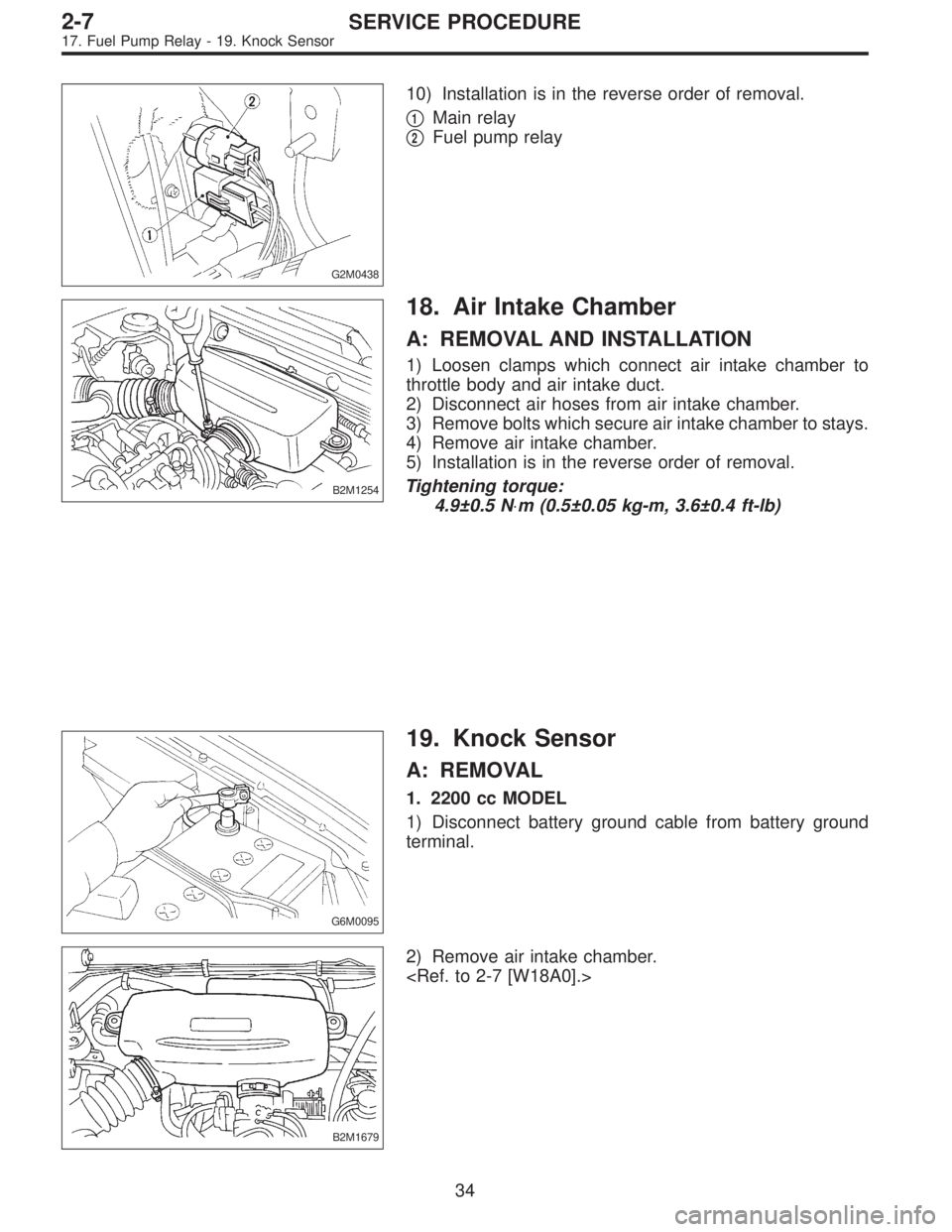
10) Installation is in the reverse order of removal.
�
1Main relay
�
2Fuel pump relay
B2M1254
18. Air Intake Chamber
A: REMOVAL AND INSTALLATION
1) Loosen clamps which connect air intake chamber to
throttle body and air intake duct.
2) Disconnect air hoses from air intake chamber.
3) Remove bolts which secure air intake chamber to stays.
4) Remove air intake chamber.
5) Installation is in the reverse order of removal.
Tightening torque:
4.9±0.5 N⋅m (0.5±0.05 kg-m, 3.6±0.4 ft-lb)
G6M0095
19. Knock Sensor
A: REMOVAL
1. 2200 cc MODEL
1) Disconnect battery ground cable from battery ground
terminal.
B2M1679
2) Remove air intake chamber.
34
2-7SERVICE PROCEDURE
17. Fuel Pump Relay - 19. Knock Sensor
Page 515 of 3342
G2M0438
10) Installation is in the reverse order of removal.
�
1Main relay
�
2Fuel pump relay
B2M1254
18. Air Intake Chamber
A: REMOVAL AND INSTALLATION
1) Loosen clamps which connect air intake chamber to
throttle body and air intake duct.
2) Disconnect air hoses from air intake chamber.
3) Remove bolts which secure air intake chamber to stays.
4) Remove air intake chamber.
5) Installation is in the reverse order of removal.
Tightening torque:
4.9±0.5 N⋅m (0.5±0.05 kg-m, 3.6±0.4 ft-lb)
G6M0095
19. Knock Sensor
A: REMOVAL
1. 2200 cc MODEL
1) Disconnect battery ground cable from battery ground
terminal.
B2M1679
2) Remove air intake chamber.
34
2-7SERVICE PROCEDURE
17. Fuel Pump Relay - 19. Knock Sensor
Page 516 of 3342
G2M0438
10) Installation is in the reverse order of removal.
�
1Main relay
�
2Fuel pump relay
B2M1254
18. Air Intake Chamber
A: REMOVAL AND INSTALLATION
1) Loosen clamps which connect air intake chamber to
throttle body and air intake duct.
2) Disconnect air hoses from air intake chamber.
3) Remove bolts which secure air intake chamber to stays.
4) Remove air intake chamber.
5) Installation is in the reverse order of removal.
Tightening torque:
4.9±0.5 N⋅m (0.5±0.05 kg-m, 3.6±0.4 ft-lb)
G6M0095
19. Knock Sensor
A: REMOVAL
1. 2200 cc MODEL
1) Disconnect battery ground cable from battery ground
terminal.
B2M1679
2) Remove air intake chamber.
34
2-7SERVICE PROCEDURE
17. Fuel Pump Relay - 19. Knock Sensor
 Remove pressure sources switching solenoid valve
from bracket.
4) Installation is in the reverse order of removal.
Tightening torque:
6.4±0.5 N⋅m (0.65±0.05 kg-m, 4.7±0.4 ft-lb)
G2M039")
 Remove pressure sources switching solenoid valve
from bracket.
4) Installation is in the reverse order of removal.
Tightening torque:
6.4±0.5 N⋅m (0.65±0.05 kg-m, 4.7±0.4 ft-lb)
G2M039")
 Remove pressure sources switching solenoid valve
from bracket.
4) Installation is in the reverse order of removal.
Tightening torque:
6.4±0.5 N⋅m (0.65±0.05 kg-m, 4.7±0.4 ft-lb)
G2M039")