Page 472 of 3342

2. 2500 cc MODEL
B2M1198A
�1Intake manifold gasket LH
�
2Intake manifold gasket RH
�
3Fuel injector pipe insulator
�
4Fuel injector pipe
�
5O-ring A
�
6O-ring B
�
7Fuel injector
�
8Insulator
�
9Fuel injector cap
�
10Plate
�
11Sealing
�
12Gasket
�
13Engine coolant hose B
�
14Air by-pass hose
�
15Idle air control solenoid valve
�
16Engine coolant hose A
�
17Nipple (AT model)
�
18Plug
�
19PCV valve�
20Purge control solenoid valve
�
21Nipple
�
22BPT
�
23BPT holder bracket
�
24Back pressure hose
�
25EGR vacuum hose A
�
26EGR vacuum pipe
�
27EGR vacuum hose C
�
28EGR valve
�
29Gasket
�
30EGR vacuum hose B
�
31EGR solenoid valve
�
32EGR pipe
�
33Pressure sensor
�
34Pressure sources switching solenoid
valve
�
35Vacuum hose A
�
36Vacuum hose B
�
37Vacuum hose C�
38Bracket
(Except Canada spec. vehicles)
�
39Bracket
(For Canada spec. vehicles)
�
40Collar
�
41Intake manifold
Tightening torque: N⋅m (kg-m, ft-lb)
T1: 3.4±0.5 (0.35±0.05, 2.5±0.4)
T2: 4.9±0.5 (0.5±0.05, 3.6±0.4)
T3: 6.4±0.5 (0.65±0.05, 4.7±0.4)
T4: 16±1.5 (1.6±0.15, 11.6±1.1)
T5: 19±1.5 (1.9±0.15, 13.7±1.1)
T6: 19±2 (1.9±0.2, 13.7±1.4)
T7: 23±3 (2.3±0.3, 16.6±2.2)
T8: 25±2 (2.5±0.2, 18.1±1.4)
T9: 34±2 (3.5±0.2, 25.3±1.4)
4
2-7COMPONENT PARTS
1. Intake Manifold
Page 473 of 3342
2. Air Intake System
B2M1166A
�1Gasket
�
2Throttle position sensor
�
3Throttle body
�
4Clamp
�
5Air intake duct
�
6By-pass hose
�
7Air intake chamber�
8Stay A
�
9Stay B (AT model)
�
10Stay C (MT model)
�
11Stay D (MT model)
�
12Spacer
�
13Bush
Tightening torque: N⋅m (kg-m, ft-lb)
T1: 2.2±0.2 (0.22±0.02, 1.6±0.1)
T2: 4.9±0.5 (0.5±0.05, 3.6±0.4)
T3: 22±2 (2.2±0.2, 15.9±1.4)
5
2-7COMPONENT PARTS
2. Air Intake System
Page 474 of 3342
3. Air Cleaner
B2M1245A
�1Mass air flow sensor bracket
�
2Mass air flow sensor ASSY
�
3Air cleaner upper cover
�
4Air cleaner element
�
5Spacer
�
6Bush�
7Clip
�
8Air cleaner case
�
9Cushion rubber
�
10Air intake duct
�
11Resonator chamber ASSY
�
12Clip
Tightening torque: N⋅m (kg-m, ft-lb)
T1: 7.4±2.0 (0.75±0.2, 5.4±1.4)
T2: 33±10 (3.4±1.0, 25±7)
6
2-7COMPONENT PARTS
3. Air Cleaner
Page 475 of 3342
B2M1225A
1. Air Cleaner and Air Intake Duct
A: REMOVAL AND INSTALLATION
1) Disconnect connector from mass air flow sensor.
B2M1226A
2) Loosen clamp which connects air intake duct to air
intake chamber.
3) Remove two clips of air cleaner upper cover.
4) Disconnect blow-by hose from air intake duct.
B2M1227
5) Remove air intake duct and air cleaner upper cover as
a unit.
6) Remove air cleaner element.
B2M1232A
7) Remove air cleaner lower case.
B2M1213
8) Installation is in the reverse order of removal.
CAUTION:
Before installing air cleaner upper cover, align holes
with protruding portions of air cleaner lower case, then
secure upper cover to lower case.
7
2-7SERVICE PROCEDURE
1. Air Cleaner and Air Intake Duct
Page 476 of 3342
B2M1214A
2. Mass Air Flow Sensor
A: REMOVAL AND INSTALLATION
1) Loosen clamps which connect air intake duct to air
intake chamber and mass air flow sensor.
2) Disconnect blow-by hose from air intake duct.
3) Remove air intake duct.
B2M1246A
4) Disconnect connector from mass air flow sensor.
G2M0390
5) Remove two clips, then remove air cleaner upper cover.
G2M0393
6) Remove mass air flow sensor from air cleaner upper
cover.
7) Installation is in the reverse order of removal.
Tightening torque:
7.4±2.0 N⋅m (0.75±0.2 kg-m, 5.4±1.4 ft-lb)
CAUTION:
Before installing air cleaner upper cover, align holes
with protruding portions of air cleaner lower case, then
secure upper cover to lower case.
8
2-7SERVICE PROCEDURE
2. Mass Air Flow Sensor
Page 477 of 3342
B2M1214A
3. Throttle Body
A: REMOVAL AND INSTALLATION
1) Loosen clamps which connect air intake duct to air
intake chamber and mass air flow sensor.
2) Disconnect blow-by hose from air intake duct.
3) Remove air intake duct.
B2M1218
4) Loosen clamp which connects air intake chamber to
throttle body.
5) Disconnect air hoses, and remove air intake chamber.
G2M0280
6) Disconnect accelerator cable�1.
7) Disconnect cruise control cable�
2. (With cruise control
model)
B2M1247
8) Disconnect connector from throttle position sensor.
B2M1248
9) Disconnect engine coolant hoses from throttle body.
9
2-7SERVICE PROCEDURE
3. Throttle Body
Page 478 of 3342
B2M1249
10) Remove bolts which install throttle body to intake
manifold.
11) Installation is in the reverse order of removal.
CAUTION:
�Always use a new gasket.
�Before installing air cleaner upper cover, align holes
with protruding portions of air cleaner lower case, then
secure upper cover to lower case.
Tightening torque:
Throttle body:
22±2 N⋅m (2.2±0.2 kg-m, 15.9±1.4 ft-lb)
Air intake chamber:
4.9±0.5 N⋅m (0.5±0.05 kg-m, 3.6±0.4 ft-lb)
B2M1225A
4. Intake Manifold
A: REMOVAL
1) Release fuel pressure.
2) Disconnect connector from mass air flow sensor.
B2M1226A
3) Loosen clamp which connects air intake duct to air
intake chamber.
4) Remove two clips of air cleaner upper cover.
5) Disconnect blow-by hose from air intake duct.
B2M1227
6) Remove air intake duct and air cleaner upper cover as
a unit.
7) Remove air cleaner element.
10
2-7SERVICE PROCEDURE
3. Throttle Body - 4. Intake Manifold
Page 479 of 3342
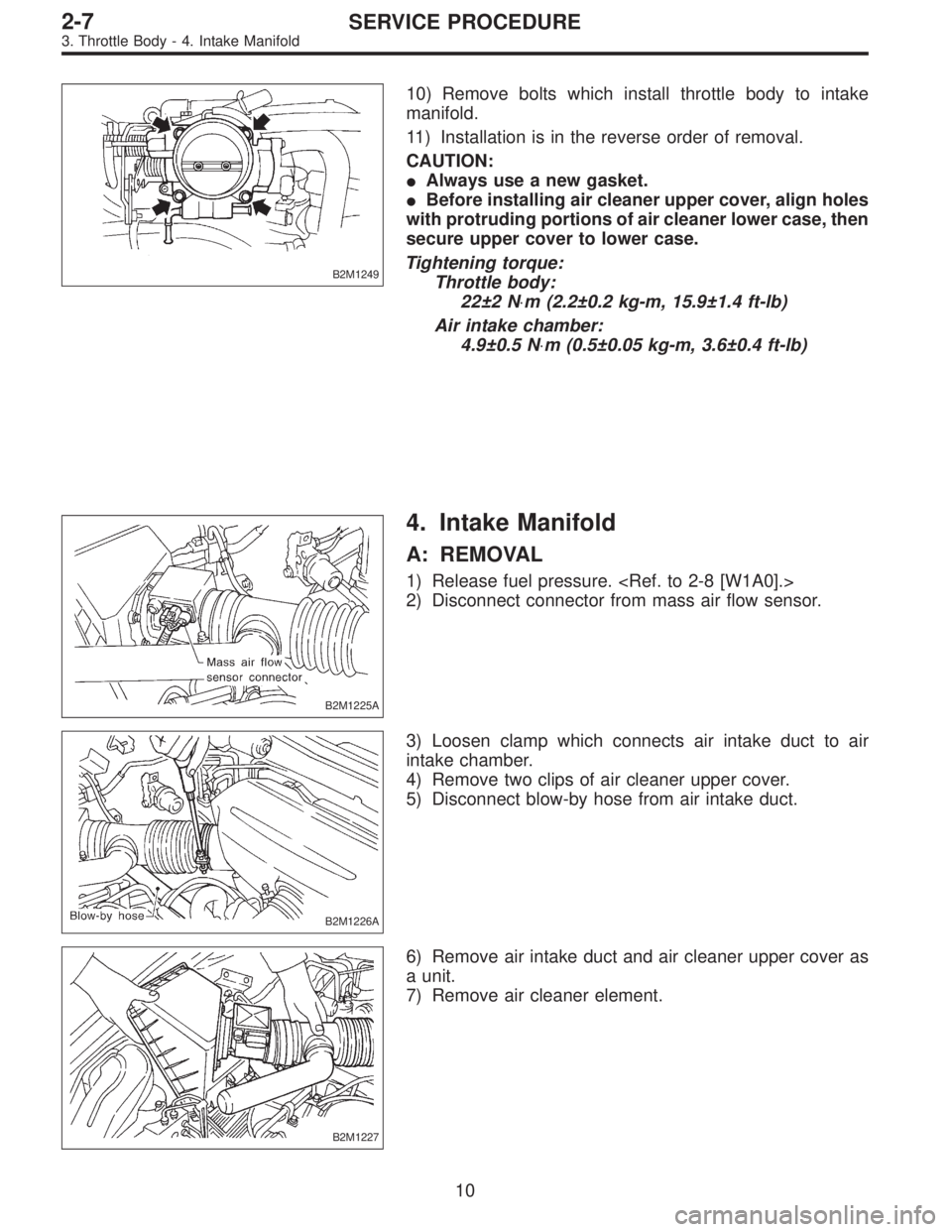
B2M1249
10) Remove bolts which install throttle body to intake
manifold.
11) Installation is in the reverse order of removal.
CAUTION:
�Always use a new gasket.
�Before installing air cleaner upper cover, align holes
with protruding portions of air cleaner lower case, then
secure upper cover to lower case.
Tightening torque:
Throttle body:
22±2 N⋅m (2.2±0.2 kg-m, 15.9±1.4 ft-lb)
Air intake chamber:
4.9±0.5 N⋅m (0.5±0.05 kg-m, 3.6±0.4 ft-lb)
B2M1225A
4. Intake Manifold
A: REMOVAL
1) Release fuel pressure.
2) Disconnect connector from mass air flow sensor.
B2M1226A
3) Loosen clamp which connects air intake duct to air
intake chamber.
4) Remove two clips of air cleaner upper cover.
5) Disconnect blow-by hose from air intake duct.
B2M1227
6) Remove air intake duct and air cleaner upper cover as
a unit.
7) Remove air cleaner element.
10
2-7SERVICE PROCEDURE
3. Throttle Body - 4. Intake Manifold


 Disconnect connector from mass air flow sensor.
B2M1226A
2) Loosen clamp which connects air intake duct to air
intake chamber")
 Loosen clamps which connect air intake duct to air
intake chamber and mass air flow sensor.
2) Disconnect blow-by hose from air intake d")
 Loosen clamps which connect air intake duct to air
intake chamber and mass air flow sensor.
2) Disconnect blow-by hose from air intake duct.
3)")