Page 503 of 3342
 When using Subaru Select Monitor;
(1) Connect Subaru Select Monitor to the data link con-
nector.
(2) Turn ignition switch to ON and SSM switch to ON.
(3) Select mode “F10”.
(4) Adjust")
G2M0096
4) When using Subaru Select Monitor;
(1) Connect Subaru Select Monitor to the data link con-
nector.
(2) Turn ignition switch to ON and SSM switch to ON.
(3) Select mode “F10”.
(4) Adjust throttle position sensor to specified data.
Condition / Specified data.
Throttle fully closed / 0.50 V
(5) Tighten throttle position sensor holding screws.
G2M0416
10. Camshaft Position Sensor
A: REMOVAL AND INSTALLATION
1) Disconnect connector from camshaft position sensor.
G2M0417
2) Remove camshaft position sensor from camshaft sup-
port LH.
3) Installation is in the reverse order of removal.
Tightening torque:
6.4±0.5 N⋅m (0.65±0.05 kg-m, 4.7±0.4 ft-lb)
B2M0355
11. Pressure Sensor (AT model)
A: REMOVAL AND INSTALLATION
1) Disconnect connector from pressure sensor.
2) Disconnect hose from pressure sensor.
B2M0356
3) Remove pressure sensor from bracket.
4) Installation is in the reverse order of removal.
Tightening torque:
6.4±0.5 N⋅m (0.65±0.05 kg-m, 4.7±0.4 ft-lb)
28
2-7SERVICE PROCEDURE
9. Throttle Position Sensor - 11. Pressure Sensor (AT model)
Page 514 of 3342
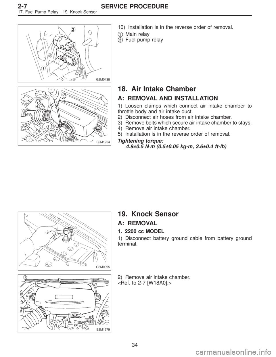
G2M0438
10) Installation is in the reverse order of removal.
�
1Main relay
�
2Fuel pump relay
B2M1254
18. Air Intake Chamber
A: REMOVAL AND INSTALLATION
1) Loosen clamps which connect air intake chamber to
throttle body and air intake duct.
2) Disconnect air hoses from air intake chamber.
3) Remove bolts which secure air intake chamber to stays.
4) Remove air intake chamber.
5) Installation is in the reverse order of removal.
Tightening torque:
4.9±0.5 N⋅m (0.5±0.05 kg-m, 3.6±0.4 ft-lb)
G6M0095
19. Knock Sensor
A: REMOVAL
1. 2200 cc MODEL
1) Disconnect battery ground cable from battery ground
terminal.
B2M1679
2) Remove air intake chamber.
34
2-7SERVICE PROCEDURE
17. Fuel Pump Relay - 19. Knock Sensor
Page 515 of 3342
G2M0438
10) Installation is in the reverse order of removal.
�
1Main relay
�
2Fuel pump relay
B2M1254
18. Air Intake Chamber
A: REMOVAL AND INSTALLATION
1) Loosen clamps which connect air intake chamber to
throttle body and air intake duct.
2) Disconnect air hoses from air intake chamber.
3) Remove bolts which secure air intake chamber to stays.
4) Remove air intake chamber.
5) Installation is in the reverse order of removal.
Tightening torque:
4.9±0.5 N⋅m (0.5±0.05 kg-m, 3.6±0.4 ft-lb)
G6M0095
19. Knock Sensor
A: REMOVAL
1. 2200 cc MODEL
1) Disconnect battery ground cable from battery ground
terminal.
B2M1679
2) Remove air intake chamber.
34
2-7SERVICE PROCEDURE
17. Fuel Pump Relay - 19. Knock Sensor
Page 516 of 3342
G2M0438
10) Installation is in the reverse order of removal.
�
1Main relay
�
2Fuel pump relay
B2M1254
18. Air Intake Chamber
A: REMOVAL AND INSTALLATION
1) Loosen clamps which connect air intake chamber to
throttle body and air intake duct.
2) Disconnect air hoses from air intake chamber.
3) Remove bolts which secure air intake chamber to stays.
4) Remove air intake chamber.
5) Installation is in the reverse order of removal.
Tightening torque:
4.9±0.5 N⋅m (0.5±0.05 kg-m, 3.6±0.4 ft-lb)
G6M0095
19. Knock Sensor
A: REMOVAL
1. 2200 cc MODEL
1) Disconnect battery ground cable from battery ground
terminal.
B2M1679
2) Remove air intake chamber.
34
2-7SERVICE PROCEDURE
17. Fuel Pump Relay - 19. Knock Sensor
Page 517 of 3342
B2M1680A
3) Remove band clip which fastens engine harness to
engine coolant hose.
B2M1681
4) Disconnect knock sensor connector.
B2M1682
5) Remove knock sensor from cylinder block.
G6M0095
2. 2500 cc MODEL
1) Disconnect battery ground cable from battery ground
terminal.
B2M1683
2) Remove air intake chamber.
35
2-7SERVICE PROCEDURE
19. Knock Sensor
Page 518 of 3342
B2M1179D
3) Remove operating cylinder. (MT vehicle only)
B2M1684
NOTE:
Place the operating cylinder where it will not interfere with
the work in process.
B2M1685A
4) Remove band clip which fastens engine harness to
engine coolant hose.
B2M1686
5) Disconnect knock sensor connector.
B2M1682
6) Remove knock sensor from cylinder block.
36
2-7SERVICE PROCEDURE
19. Knock Sensor
Page 519 of 3342
B2M1682A
B: INSTALLATION
1. 2200 cc MODEL
1) Install knock sensor to cylinder block.
Tightening torque:
23.5±2.9 N⋅m (2.4±0.3 kg-m, 17.3±2.1 ft-lb)
NOTE:
The extraction area of the knock sensor cord must be posi-
tioned at a 45°angle relative to the engine rear.
B2M1681
2) Connect knock sensor connector.
B2M1687A
NOTE:
The knock sensor cord must pass between the engine
harness and engine coolant hose.
B2M1680A
3) Fasten engine harness to engine coolant hose with
band clip.
NOTE:
Make sure that the throttle linkage does not interfere with
other parts in the operating area.
B2M1679
4) Install air intake chamber.
37
2-7SERVICE PROCEDURE
19. Knock Sensor
Page 520 of 3342
G6M0095
5) Connect battery ground cable to battery ground termi-
nal.
B2M1682A
2. 2500 cc MODEL
1) Install knock sensor to cylinder block.
Tightening torque:
23.5±2.9 N⋅m (2.4±0.3 kg-m, 17.3±2.1 ft-lb)
NOTE:
The extraction area of the knock sensor cord must be posi-
tioned at a 45°angle relative to the engine rear.
B2M1686
2) Connect knock sensor connector.
B2M1688A
NOTE:
The connector must be connected to the engine front end
of the engine coolant hose.
B2M1689A
38
2-7SERVICE PROCEDURE
19. Knock Sensor


 Remove band clip which fastens engine harness to
engine coolant hose.
B2M1681
4) Disconnect knock sensor connector.
B2M1682
5) Remove knock sensor from cylinder block.
G6M0095
2. 2500 cc M")
 Remove operating cylinder. (MT vehicle only)
B2M1684
NOTE:
Place the operating cylinder where it will not interfere with
the work in process.
B2M1685A
4) Remove band clip which fastens eng")
 Install knock sensor to cylinder block.
Tightening torque:
23.5±2.9 N⋅m (2.4±0.3 kg-m, 17.3±2.1 ft-lb)
NOTE:
The extraction area of the knock sensor c")
 Connect battery ground cable to battery ground termi-
nal.
B2M1682A
2. 2500 cc MODEL
1) Install knock sensor to cylinder block.
Tightening torque:
23.5±2.9 N⋅m (2.4±0.3 kg-m, 17.3±2.1")