Page 605 of 3342
B2M0335
(3) Disconnect connector from rear oxygen sensor.
G2M0291
(4) Separate center exhaust pipe from rear exhaust
pipe.
B2M0313
(5) Remove bolt which installs center exhaust pipe on
hunger bracket.
(6) Take off front and center exhaust pipes.
CAUTION:
Exhaust pipe will drop when all bolts are removed. So,
hold it when removing the last bolt.
G2M0292
13) Remove nuts which hold lower side of transmission to
engine.
G2M0293
14) Remove nuts which install front cushion rubber onto
front crossmember.
17
2-11SERVICE PROCEDURE
2. Engine
Page 612 of 3342
 Install front exhaust pipe and center exhaust pipe.
12) Connect hoses, connectors and cables.
(1) Connect the following hoses.
�Fuel delivery hose, return hose and evaporation
hose
�Heater inlet a")
11) Install front exhaust pipe and center exhaust pipe.
12) Connect hoses, connectors and cables.
(1) Connect the following hoses.
�Fuel delivery hose, return hose and evaporation
hose
�Heater inlet and outlet hoses
�Brake booster vacuum hose
(2) Connect the following connectors.
�Engine ground terminal
�Engine harness connectors
�Front oxygen sensor connector
�Rear oxygen sensor connector
�Alternator connector and terminal
�A/C compressor connectors (With A/C)
(3) Connect the following cables.
�Accelerator cable
�Cruise control cables (With cruise control)
�Clutch cable
�Clutch release spring
CAUTION:
After connecting each cable, adjust them.
B2M1168
13) Install air intake system.
(1) Install air cleaner element.
(2) Install air intake duct with air cleaner upper cover.
B2M0030
(3) Connect connector to mass air flow sensor.
G2M0270
14) Install A/C pressure hoses. (With A/C)
CAUTION:
Use new O-rings.
Tightening torque:
25±7 N⋅m (2.5±0.7 kg-m, 18.1±5.1 ft-lb)
24
2-11SERVICE PROCEDURE
2. Engine
Page 617 of 3342
B2M1170
1) Open front hood fully, and support with stay.
2) Disconnect battery ground terminal.
3) Remove air intake duct and chamber.
G2M0544
4) Disconnect connectors and cables.
(1) Disconnect the following connectors.
�Front oxygen sensor connector
G2M0307
�Transmission harness connector
�Transmission ground terminal
B2M0337
�Neutral position switch connector (MT model)
�Back-up light switch connector (MT model)
G2M0827
�Vehicle speed sensor 2
29
2-11SERVICE PROCEDURE
3. Transmission
Page 620 of 3342
G2M0290
14) Remove exhaust system.
(1) Remove nuts which install front exhaust pipe onto
engine.
B2M0335
(2) Disconnect connector from rear oxygen sensor.
G2M0291
(3) Separate center exhaust pipe from rear exhaust
pipe.
B2M0313
(4) Remove bolt which installs center exhaust pipe to
hanger bracket.
(5) Take off front and center exhaust pipes.
G2M0315
(6) Remove rear exhaust pipe. (AWD model)
CAUTION:
When removing exhaust pipes, be careful each
exhaust pipe does not drop out.
32
2-11SERVICE PROCEDURE
3. Transmission
Page 632 of 3342
B2M0335
(7) Connect connector to rear oxygen sensor.
B2M1300A
17) Install clutch damper. (Hydraulic clutch model)
Tightening torque:
25±7 N⋅m (2.5±0.7 kg-m, 18.1±5.1 ft-lb)
G2M0312
18) Install transmission connector holder bracket.
B2M0031
19) Install ATF level gauge. (AT model)
44
2-11SERVICE PROCEDURE
3. Transmission
Page 633 of 3342
20) Connect connectors and cables.
(1) Connect the following connectors.
�Transmission harness connectors
�Transmission ground terminal
�Front oxygen sensor connector
�Vehicle speed sensor 2
�Neutral position switch connector (MT model)
�Back-up light switch connector (MT model)
(2) Connect the following cables.
�Cruise control cable
(With cruise control model)
�Clutch cable
G2M0309
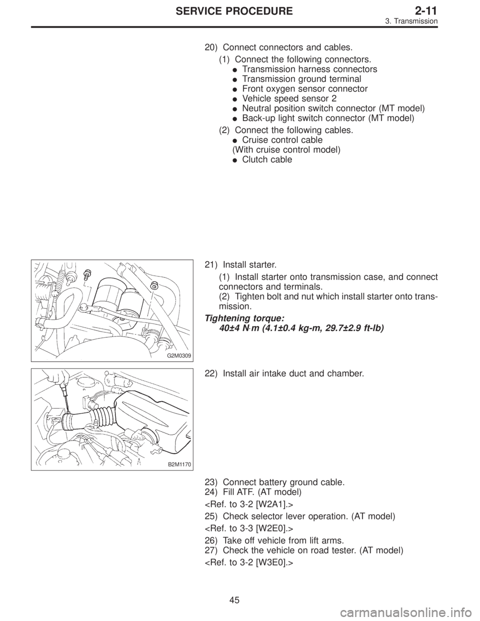
21) Install starter.
(1) Install starter onto transmission case, and connect
connectors and terminals.
(2) Tighten bolt and nut which install starter onto trans-
mission.
Tightening torque:
40±4 N⋅m (4.1±0.4 kg-m, 29.7±2.9 ft-lb)
B2M1170
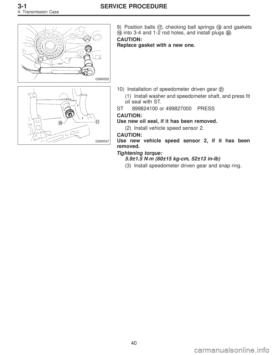
22) Install air intake duct and chamber.
23) Connect battery ground cable.
24) Fill ATF. (AT model)
25) Check selector lever operation. (AT model)
26) Take off vehicle from lift arms.
27) Check the vehicle on road tester. (AT model)
45
2-11SERVICE PROCEDURE
3. Transmission
Page 668 of 3342
 Drive out spring pin�6, and pull out 3-4 fork rod�7and
shifter fork�
8.
NOTE:
When removing rod, keep other rods in neutral. Also, when
pulling out straight pin, remove it toward inside of")
B3M0333B
3) Drive out spring pin�6, and pull out 3-4 fork rod�7and
shifter fork�
8.
NOTE:
When removing rod, keep other rods in neutral. Also, when
pulling out straight pin, remove it toward inside of case so
that it may not hit against case.
4) Drive out straight pin�
9, and pull out 1-2 fork rod�10and
shifter fork�
11.
G3M0602
5) Pull out straight pin�12, and remove idler gear shaft�13,
reverse idler gear�
14and washer�15.
6) Remove outer snap ring�
16, and pull out reverse shifter
rod arm�
17from reverse fork rod�18. Then take out ball,
spring and interlock plunger from rod.
And then remove rod.
NOTE:
When pulling out reverse shifter rod arm, be careful not to
let ball pop out of arm.
7) Remove reverse shifter lever�
19.
G3M0546
8) Remove differential side retainers using ST.
ST 499787000 WRENCH ASSY
G3M0547
9) Remove outer snap ring�20and pull out speedometer
driven gear�
21. Next, remove vehicle speed sensor 2, oil
seal, speedometer shaft�
22and washer.
36
3-1SERVICE PROCEDURE
4. Transmission Case
Page 672 of 3342
G3M0552
9) Position balls�17, checking ball springs�18and gaskets
�
19into 3-4 and 1-2 rod holes, and install plugs�20.
CAUTION:
Replace gasket with a new one.
G3M0547
10) Installation of speedometer driven gear�21
(1) Install washer and speedometer shaft, and press fit
oil seal with ST.
ST 899824100 or 499827000 PRESS
CAUTION:
Use new oil seal, if it has been removed.
(2) Install vehicle speed sensor 2.
CAUTION:
Use new vehicle speed sensor 2, if it has been
removed.
Tightening torque:
5.9±1.5 N⋅m (60±15 kg-cm, 52±13 in-lb)
(3) Install speedometer driven gear and snap ring.
40
3-1SERVICE PROCEDURE
4. Transmission Case
 Disconnect connector from rear oxygen sensor.
G2M0291
(4) Separate center exhaust pipe from rear exhaust
pipe.
B2M0313
(5) Remove bolt which installs center exhaust pipe on
hunger bracket.")
 Open front hood fully, and support with stay.
2) Disconnect battery ground terminal.
3) Remove air intake duct and chamber.
G2M0544
4) Disconnect connectors and cables.
(1) Disconnect the f")
 Remove exhaust system.
(1) Remove nuts which install front exhaust pipe onto
engine.
B2M0335
(2) Disconnect connector from rear oxygen sensor.
G2M0291
(3) Separate center exhaust pipe from")
 Connect connector to rear oxygen sensor.
B2M1300A
17) Install clutch damper. (Hydraulic clutch model)
Tightening torque:
25±7 N⋅m (2.5±0.7 kg-m, 18.1±5.1 ft-lb)
G2M0312
18) Install tr")