Page 856 of 3342
G3M0874
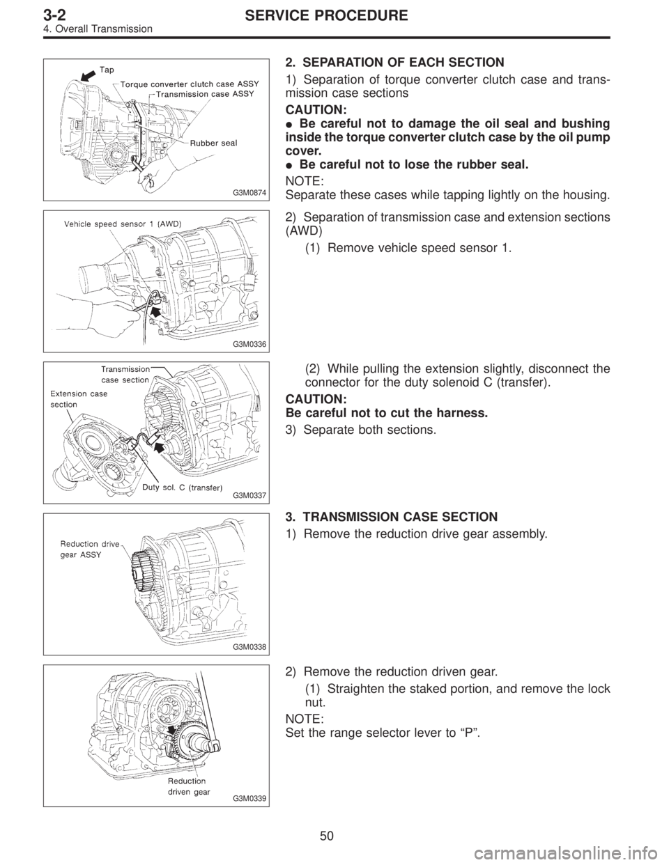
2. SEPARATION OF EACH SECTION
1) Separation of torque converter clutch case and trans-
mission case sections
CAUTION:
�Be careful not to damage the oil seal and bushing
inside the torque converter clutch case by the oil pump
cover.
�Be careful not to lose the rubber seal.
NOTE:
Separate these cases while tapping lightly on the housing.
G3M0336
2) Separation of transmission case and extension sections
(AWD)
(1) Remove vehicle speed sensor 1.
G3M0337
(2) While pulling the extension slightly, disconnect the
connector for the duty solenoid C (transfer).
CAUTION:
Be careful not to cut the harness.
3) Separate both sections.
G3M0338
3. TRANSMISSION CASE SECTION
1) Remove the reduction drive gear assembly.
G3M0339
2) Remove the reduction driven gear.
(1) Straighten the staked portion, and remove the lock
nut.
NOTE:
Set the range selector lever to“P”.
50
3-2SERVICE PROCEDURE
4. Overall Transmission
Page 864 of 3342
G3M0371
5) Remove the snap ring. Then remove the speedometer
driven gear.
G3M0372
6) Remove vehicle speed sensor 2.
7) Tap out the speedometer shaft to the outside of the
case, and remove the oil seal.
G3M0373
5. EXTENSION SECTION
1) Take out the transfer clutch by lightly tapping the end of
the rear drive shaft.
CAUTION:
Be careful not to damage the oil seal in the extension.
G3M0867
2) Remove duty solenoid C, transfer valve body and the
transfer pipe.
CAUTION:
�Take out the inlet filter.
�Do not damage the O-ring.
�Be careful not to bend the pipe.
B3M0831A
3) Take out the roller bearing inner race with ST.
ST 398527700 PULLER
4) Take out the roller bearing outer race with ST.
NOTE:
Hook ST in the inner side of the roller bearing outer race.
ST 398527700 PULLER
58
3-2SERVICE PROCEDURE
4. Overall Transmission
Page 865 of 3342
 Check the appearance of each component and clean.
CAUTION:
Make sure each part is free of harmful cuts, damage
and other")
B: ASSEMBLY OF OVERALL TRANSMISSION
1. TORQUE CONVERTER CLUTCH CASE SECTION
1) Check the appearance of each component and clean.
CAUTION:
Make sure each part is free of harmful cuts, damage
and other faults.
G3M0377
2) Install the washer and snap ring to the speedometer
shaft with ST, and set the oil seal. Then force-fit the shaft
to the torque converter clutch case.
ST 499827000 PRESS
3) Install vehicle speed sensor 2.
CAUTION:
Use new vehicle speed sensor 2, if it has been
removed.
Tightening torque:
5.9±1.5 N⋅m (60±15 kg-cm, 52±13 in-lb)
G3M0378
4) Install the speedometer driven gear to the speedometer
shaft, and secure with a snap ring.
G3M0379
5) Force-fit the oil seal to the torque converter clutch case
with ST.
ST 398437700 DRIFT
G3M0380
6) Install the differential assembly to the case, paying spe-
cial attention not to damage the speedometer gears (drive
and driven) and the inside of the case (particularly, the dif-
ferential side retainer contact surface).
59
3-2SERVICE PROCEDURE
4. Overall Transmission
Page 881 of 3342
G3M0367
2) Install and route the transmission harness.
CAUTION:
Be careful not to damage the harness.
B3M0418A
3) Install the control valve assembly.
(1) Set the select lever in range“2”.
(2) Install the two brackets, ATF temperature sensor
and the control valve by engaging the manual valve and
manual lever, then tighten the 17 bolts.
Tightening torque:
8±1 N⋅m (0.8±0.1 kg-m, 5.8±0.7 ft-lb)
CAUTION:
�Be careful not to pinch the harness roll the gasket.
�Tighten the control valve mounting bolts evenly.
B3M0419A
4) Install the oil strainer to the control valve. Be careful not
to cut or break the O-ring. Then tighten four bolts.
Tightening torque:
8±1 N⋅m (0.8±0.1 kg-m, 5.8±0.7 ft-lb)
B3M0420A
5) Secure four connectors.
75
3-2SERVICE PROCEDURE
4. Overall Transmission
Page 883 of 3342
 Install the transfer clutch assembly to the case.
CAUTION:
Be careful not to damage the seal rings.
NOTE:
Insert the clutch assembly fully into position until the bear-
ing shoulder bottoms")
G3M0894
3) Install the transfer clutch assembly to the case.
CAUTION:
Be careful not to damage the seal rings.
NOTE:
Insert the clutch assembly fully into position until the bear-
ing shoulder bottoms.
G3M0429
6. CONNECTION OF EACH SECTION
1) Install vehicle speed sensor 1 on transmission case.
[FWD only]
Tightening torque:
7±1 N⋅m (0.7±0.1 kg-m, 5.1±0.7 ft-lb)
2) Install oil pipe.
G3M0339
3) Install the reduction driven gear.
4) Install the parking pawl and shaft, set the select lever in
the“P”range and tighten the drive pinion lock nut.
Tightening torque:
98±5 N⋅m (10.0±0.5 kg-m, 72.3±3.6 ft-lb)
NOTE:
After tightening, stake the lock nut securely.
G3M0895
5) Install the reduction drive gear assembly.
CAUTION:
Align mark on reduction drive gear with mark on driven
gear during installation.
NOTE:
Insert it fully into position until the bearing shoulder bot-
toms.
G3M0430
6) Measurement and adjustment of extension end play
(1) Measure distance L from end of extension case and
rear drive shaft with ST. (On FWD models, measure
distance from end of case to point at bearing location.)
ST 398643600 GAUGE
Unit: mm
L = Measured value�15
77
3-2SERVICE PROCEDURE
4. Overall Transmission
Page 885 of 3342
 Installation of extension case (AWD), transmission
cover (FWD) and transmission case.
�AWD model:
(1) Attach the selected thrust needle bearing to the end
surface of reduction drive gear wi")
G3M0896
7) Installation of extension case (AWD), transmission
cover (FWD) and transmission case.
�AWD model:
(1) Attach the selected thrust needle bearing to the end
surface of reduction drive gear with vaseline.
(2) Set the parking return spring.
(3) Remove the transfer clutch from the extension
case.
Set the needle bearing on the reduction drive shaft and
then install transfer clutch to the transfer clutch hub.
NOTE:
Be sure to engage the spline teeth correctly.
(4) With gasket inserted between them, install the
extension case to the transmission case.
CAUTION:
�Be sure to use a new gasket.
�After inserting the extension case halfway, connect
the connector for duty solenoid C. Be careful not to
jam the cord in the case.
�Be careful not to damage the rear drive shaft seal
ring.
(5) Tighten bolts to secure the case.
Tightening torque:
25±2 N⋅m (2.5±0.2 kg-m, 18.1±1.4 ft-lb)
�FWD model:
(1) Attach selected shim to transmission cover using
vaseline.
(2) Set the parking return spring.
(3) After positioning gasket, assemble transmission
cover and transmission case.
NOTE:
While aligning bearings, parking shaft, reduction driven
gear, etc. assemble the two cases.
(4) Tighten bolts.
Tightening torque:
25±2 N⋅m (2.5±0.2 kg-m, 18.1±1.4 ft-lb)
G3M0336
7. EXTERNAL PARTS
1) Install the vehicle speed sensor 1. (AWD only)
Tightening torque:
7±1 N⋅m (0.7±0.1 kg-m, 5.1±0.7 ft-lb)
79
3-2SERVICE PROCEDURE
4. Overall Transmission
Page 919 of 3342
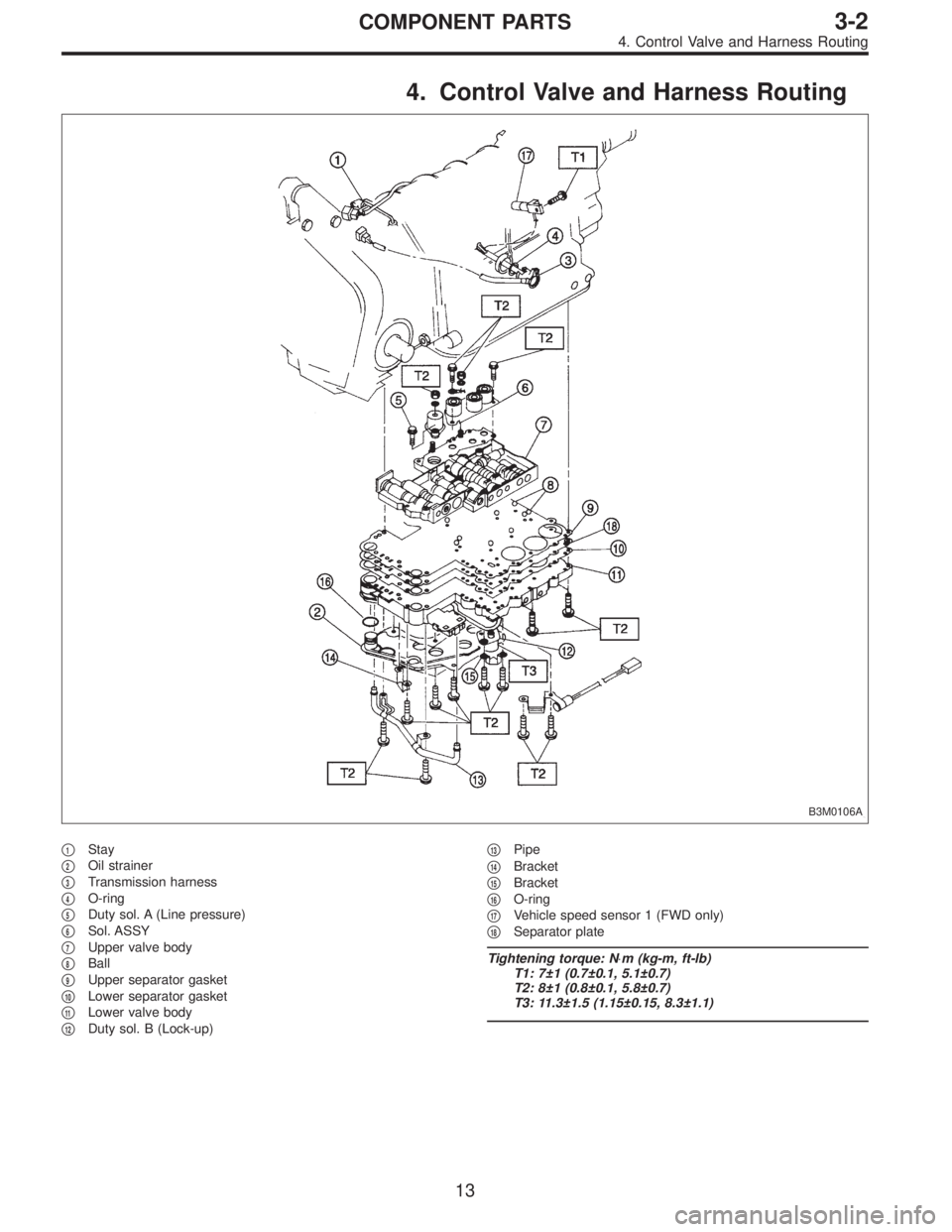
4. Control Valve and Harness Routing
B3M0106A
�1Stay
�
2Oil strainer
�
3Transmission harness
�
4O-ring
�
5Duty sol. A (Line pressure)
�
6Sol. ASSY
�
7Upper valve body
�
8Ball
�
9Upper separator gasket
�
10Lower separator gasket
�
11Lower valve body
�
12Duty sol. B (Lock-up)�
13Pipe
�
14Bracket
�
15Bracket
�
16O-ring
�
17Vehicle speed sensor 1 (FWD only)
�
18Separator plate
Tightening torque: N⋅m (kg-m, ft-lb)
T1: 7±1 (0.7±0.1, 5.1±0.7)
T2: 8±1 (0.8±0.1, 5.8±0.7)
T3: 11.3±1.5 (1.15±0.15, 8.3±1.1)
13
3-2COMPONENT PARTS
4. Control Valve and Harness Routing
Page 926 of 3342
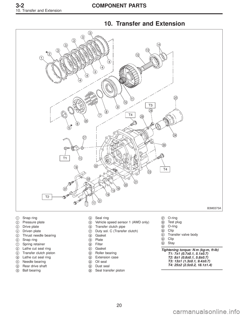
10. Transfer and Extension
B3M0375A
�1Snap ring
�
2Pressure plate
�
3Drive plate
�
4Driven plate
�
5Thrust needle bearing
�
6Snap ring
�
7Spring retainer
�
8Lathe cut seal ring
�
9Transfer clutch piston
�
10Lathe cut seal ring
�
11Needle bearing
�
12Rear drive shaft
�
13Ball bearing�
14Seal ring
�
15Vehicle speed sensor 1 (AWD only)
�
16Transfer clutch pipe
�
17Duty sol. C (Transfer clutch)
�
18Gasket
�
19Plate
�
20Filter
�
21Gasket
�
22Roller bearing
�
23Extension case
�
24Oil seal
�
25Dust seal
�
26Seal transfer piston�
27O-ring
�
28Test plug
�
29O-ring
�
30Clip
�
31Transfer valve body
�
32Clip
�
33Stay
Tightening torque: N⋅m (kg-m, ft-lb)
T1: 7±1 (0.7±0.1, 5.1±0.7)
T2: 8±1 (0.8±0.1, 5.8±0.7)
T3: 13±1 (1.3±0.1, 9.4±0.7)
T4: 25±2 (2.5±0.2, 18.1±1.4)
20
3-2COMPONENT PARTS
10. Transfer and Extension
 Remove the snap ring. Then remove the speedometer
driven gear.
G3M0372
6) Remove vehicle speed sensor 2.
7) Tap out the speedometer shaft to the outside of the
case, and remove the oil seal")
 Install and route the transmission harness.
CAUTION:
Be careful not to damage the harness.
B3M0418A
3) Install the control valve assembly.
(1) Set the select lever in range“2”.
(2) Inst")