Page 1174 of 3342
6. Replacement of Rear DOJ and BJ
Boots
A: REMOVAL
1) Disconnect ground cable from battery.
2) Lift-up vehicle, and remove rear wheel cap and wheels.
NOTE:
Axle nut need not be removed.
3) Remove A.B.S. sensor clamps and parking brake cable
bracket.
4) Disconnect stabilizer link from lateral link.
5) Remove bolts which secure lateral link assembly to rear
housing.
6) Remove bolts which secure trailing link assembly to
rear housing.
7) Remove crossmember reinforcement lower from cross-
member (4 door model only).
G4M0994
8) Remove DOJ from rear differential using ST.
ST 28099PA100 DRIVE SHAFT REMOVER
NOTE:
The side spline shaft circlip comes out together with the
shaft.
G4M0995
CAUTION:
Be careful not to damage side bearing retainer. Always
use bolt as shown in figure, as supporting point for ST
during removal.
ST 28099PA100 DRIVE SHAFT REMOVER
B: INSTALLATION
1) Install DOJ and BJ boots to drive shaft.
47
4-2SERVICE PROCEDURE
6. Replacement of Rear DOJ and BJ Boots
Page 1175 of 3342
B4M0549A
2) Using ST, install DOJ into differential.
ST 28099PA090 SIDE OIL SEAL PROTECTOR
B4M0550A
3) Insert DOJ spline end into bore of side oil seal, and
remove ST.
CAUTION:
Do not allow DOJ splines to damage side oil seal.
ST 28099PA090 SIDE OIL SEAL PROTECTOR
G3M0050
4) Align DOJ and differential splines.
5) Push housing to insert DOJ into differential.
NOTE:
Make sure DOJ is inserted properly.
CAUTION:
Discard old self-locking nut. Replace with a new one.
6) Connect rear housing assembly to trailing link
assembly, and tighten self-locking nut.
7) Connect rear housing assembly to lateral link assembly,
and tighten self-locking nut.
8) Connect stabilizer link to lateral link.
9) Install crossmember reinforcement lower to crossmem-
ber (4 door model only).
10) Install A.B.S. sensor clamps and parking brake cable
bracket.
48
4-2SERVICE PROCEDURE
6. Replacement of Rear DOJ and BJ Boots
Page 1214 of 3342
 Disconnect battery negative terminal.
2) Disconnect both oxygen sensor and exhaust gas tem-
perature warning sensor connectors from front exhaust
pipe assembly.
WARNING:
Be careful as ex")
A: REMOVAL
1) Disconnect battery negative terminal.
2) Disconnect both oxygen sensor and exhaust gas tem-
perature warning sensor connectors from front exhaust
pipe assembly.
WARNING:
Be careful as exhaust pipe is hot.
3) Raise vehicle with a jack and remove front wheel.
4) Disconnect front exhaust pipe assembly.
G4M0097
5) Remove cotter pin and castle nut. Using a puller,
remove tie-rod end from knuckle arm.
G4M0098
6) Remove jack-up plate and stabilizer.
G4M0786
7) Disconnect one pipe joint A from center of gearbox
assembly, and connect a vinyl hose to it. While turning
steering wheel to the left and right, drain fluid through the
hose. Similarly, drain fluid from the other pipe joint B.
G4M0787
8) Remove lower and upper bolts from universal joint, and
remove universal joint in the upward direction.
NOTE:
Scribe alignment marks on universal joint so that it can be
reassembled at the original serration.
30
4-3SERVICE PROCEDURE
4. Steering Gearbox (Power Steering System) [RHD model]
Page 1297 of 3342
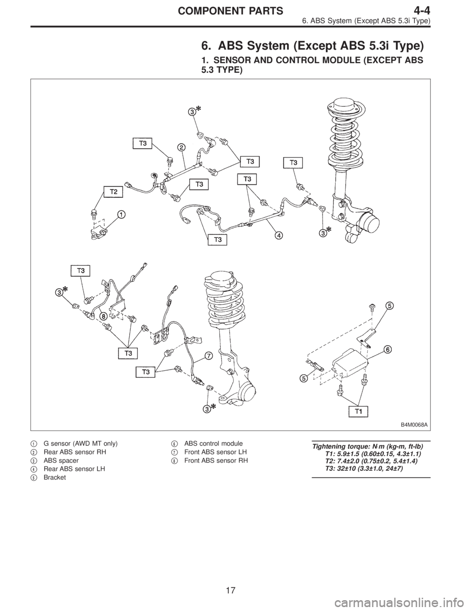
6. ABS System (Except ABS 5.3i Type)
1. SENSOR AND CONTROL MODULE (EXCEPT ABS
5.3 TYPE)
B4M0068A
�1G sensor (AWD MT only)
�
2Rear ABS sensor RH
�
3ABS spacer
�
4Rear ABS sensor LH
�
5Bracket�
6ABS control module
�
7Front ABS sensor LH
�
8Front ABS sensor RH
Tightening torque: N⋅m (kg-m, ft-lb)
T1: 5.9±1.5 (0.60±0.15, 4.3±1.1)
T2: 7.4±2.0 (0.75±0.2, 5.4±1.4)
T3: 32±10 (3.3±1.0, 24±7)
17
4-4COMPONENT PARTS
6. ABS System (Except ABS 5.3i Type)
Page 1299 of 3342
3. SENSOR AND CONTROL MODULE (ABS 5.3 TYPE)
B4M1044A
�1G sensor (AWD only)
�
2Rear ABS sensor RH
�
3ABS spacer
�
4Rear ABS sensor LH�
5Bracket
�
6ABS control module
�
7Front ABS sensor LH
�
8Front ABS sensor RH
Tightening torque: N⋅m (kg-m, ft-lb)
T1: 7.4±2.0 (0.75±0.2, 5.4±1.4)
T2: 32±10 (3.3±1.0, 24±7)
19
4-4COMPONENT PARTS
6. ABS System (Except ABS 5.3i Type)
Page 1303 of 3342
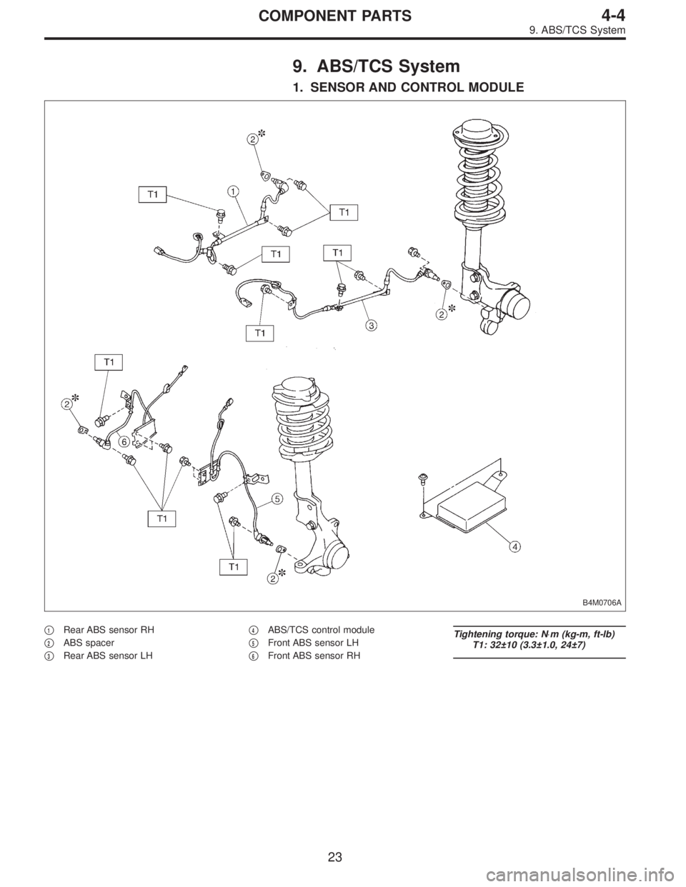
9. ABS/TCS System
1. SENSOR AND CONTROL MODULE
B4M0706A
�1Rear ABS sensor RH
�
2ABS spacer
�
3Rear ABS sensor LH�
4ABS/TCS control module
�
5Front ABS sensor LH
�
6Front ABS sensor RH
Tightening torque: N⋅m (kg-m, ft-lb)
T1: 32±10 (3.3±1.0, 24±7)
23
4-4COMPONENT PARTS
9. ABS/TCS System
Page 1305 of 3342
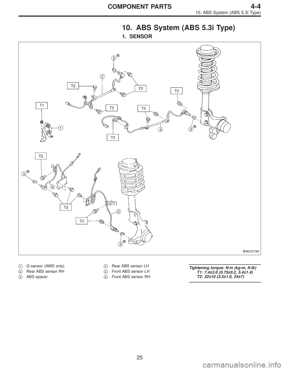
10. ABS System (ABS 5.3i Type)
1. SENSOR
B4M1219A
�1G sensor (AWD only)
�
2Rear ABS sensor RH
�
3ABS spacer�
4Rear ABS sensor LH
�
5Front ABS sensor LH
�
6Front ABS sensor RH
Tightening torque: N⋅m (kg-m, ft-lb)
T1: 7.4±2.0 (0.75±0.2, 5.4±1.4)
T2: 32±10 (3.3±1.0, 24±7)
25
4-4COMPONENT PARTS
10. ABS System (ABS 5.3i Type)
Page 1354 of 3342
14. ABS Sensor
A: REMOVAL
1. FRONT ABS SENSOR
1) Disconnect front ABS sensor connector located in
engine compartment.
B4M0079A
2) Remove bolts which secure sensor harness to strut.
G4M0451
3) Remove bolts which secure sensor harness to body.
G4M0443
4) Remove bolts which secure front ABS sensor to
housing, and remove front ABS sensor.
CAUTION:
�Be careful not to damage pole piece located at tip of
the sensor and teeth faces during removal.
�Do not pull sensor harness during removal.
5) Remove front disc brake caliper and disc rotor from
housing after removing front tire.
6) Remove front drive shaft and housing and hub assem-
bly.
72
4-4SERVICE PROCEDURE
14. ABS Sensor
 Disconnect ground cable from battery.
2) Lift-up vehicle, and remove rear wheel cap and wheels.
NOTE:
Axle nut need not be removed.
3) Remove A.B.")
 Using ST, install DOJ into differential.
ST 28099PA090 SIDE OIL SEAL PROTECTOR
B4M0550A
3) Insert DOJ spline end into bore of side oil seal, and
remove ST.
CAUTION:
Do not allow DOJ spline")

 Disconnect front ABS sensor connector located in
engine compartment.
B4M0079A
2) Remove bolts which secure sensor harness to strut.
G4M0451
3) Remove b")