Page 1642 of 3342
![SUBARU LEGACY 1997 Service Repair Manual B5M0048A
3. CENTER PILLAR UPPER
<Ref. to 5-3 [C500].>
1) Remove front pillar upper trim.
2) Remove upper anchor of front seat belt.
3) Remove center pillar upper trim panel.
4) Installation is in the](/manual-img/17/57434/w960_57434-1641.png "SUBARU LEGACY 1997 Service Repair Manual B5M0048A
3. CENTER PILLAR UPPER
<Ref. to 5-3 [C500].>
1) Remove front pillar upper trim.
2) Remove upper anchor of front seat belt.
3) Remove center pillar upper trim panel.
4) Installation is in the")
B5M0048A
3. CENTER PILLAR UPPER
1) Remove front pillar upper trim.
2) Remove upper anchor of front seat belt.
3) Remove center pillar upper trim panel.
4) Installation is in the reverse order of removal.
CAUTION:
�The left and right ELR’s are not mutually inter-
changeable because different sensors are used.
�Be careful not to twist belts during installation.
G5M0363
4. FRONT PILLAR UPPER
Remove front pillar upper trim panel.
CAUTION:
Be sure to securely hook pawls of front pillar upper
trim panel on body flange.
B5M0043A
5. REAR PILLAR UPPER
1) Remove rear seat cushion and backrest.
2) Remove rear seat belt. (Lower anchor bolt)
3) Remove rear pillar upper trim panel.
[C500].>
4) Installation is in the reverse order of removal.
CAUTION:
Be sure to securely hook pawls of rear pillar upper trim
panel on body flange.
B5M0049
6. REAR PILLAR LOWER
1) Remove side sill rear upper cover trim.
2) Remove rear pillar lower trim.
B5M0044A
7. REAR QUARTER PILLAR UPPER
1) Remove rear seat belt. (Upper anchor bolt)
2) Remove cap strut.
3) Remove rear quarter upper front trim�
1.
4) Remove rear quarter upper rear trim�
2.
5) Installation is in the reverse order of removal.
CAUTION:
Be sure to securely hook pawls of rear quarter pillar
trim panel on body flange.
14
5-3SERVICE PROCEDURE
5. Inner Trim Panel
Page 1652 of 3342
1. SRS Airbag
1. LHD MODEL
B5M0401A
�1Combination switch ASSY with roll connector
�
2TORX®bolt
�
3Airbag module ASSY (Driver)
�
4Airbag module ASSY (Passenger)
�
5BRKT B
�
6BRKT P AB
�
7BRKT SD A
�
8Front sensor ASSY RH
�
9Grommet
�
10TORX®bolt
�
11Airbag control module
�
12Protector RH
�
13Protector LH
�
14Airbag main harness
�
15Front sensor ASSY LH
Tightening torque: N⋅m (kg-m, ft-lb)
T1: 1.8±0.5 (0.18±0.05, 1.3±0.4)
T2: 2.5±0.5 (0.25±0.05, 1.8±0.4)
T3: 4.4±1.5 (0.45±0.15, 3.3±1.1)
T4: 7.4±0.5 (0.75±0.05, 5.4±0.4)
T5: 10±2 (1.0±0.2, 7.2±1.4)
T6: 20±4 (2.0±0.4, 14.5±2.9)
T7: 32±10 (3.3±1.0, 23.9±7.2)
2
5-5COMPONENT PARTS
1. SRS Airbag
Page 1653 of 3342
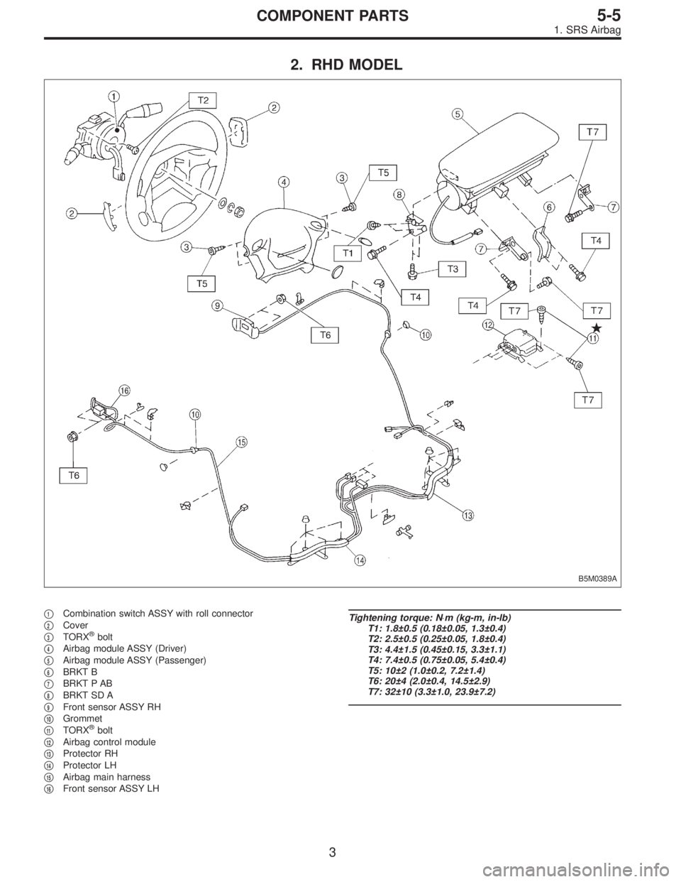
2. RHD MODEL
B5M0389A
�1Combination switch ASSY with roll connector
�
2Cover
�
3TORX®bolt
�
4Airbag module ASSY (Driver)
�
5Airbag module ASSY (Passenger)
�
6BRKT B
�
7BRKT P AB
�
8BRKT SD A
�
9Front sensor ASSY RH
�
10Grommet
�
11TORX®bolt
�
12Airbag control module
�
13Protector RH
�
14Protector LH
�
15Airbag main harness
�
16Front sensor ASSY LH
Tightening torque: N⋅m (kg-m, in-lb)
T1: 1.8±0.5 (0.18±0.05, 1.3±0.4)
T2: 2.5±0.5 (0.25±0.05, 1.8±0.4)
T3: 4.4±1.5 (0.45±0.15, 3.3±1.1)
T4: 7.4±0.5 (0.75±0.05, 5.4±0.4)
T5: 10±2 (1.0±0.2, 7.2±1.4)
T6: 20±4 (2.0±0.4, 14.5±2.9)
T7: 32±10 (3.3±1.0, 23.9±7.2)
3
5-5COMPONENT PARTS
1. SRS Airbag
Page 1654 of 3342
G5M0291
1. Precaution
1) If any of the airbag system parts such as sensors, air-
bag module, airbag control module and harness are dam-
aged or deformed, replace with new genuine parts.
G5M0292
2) When servicing, be sure to turn the ignition switch off,
disconnect the negative (�) battery terminal then the posi-
tive (+) terminal in advance, and wait for more than 20
seconds before starting work.
G5M0293
3) When checking the system, be sure to use a digital cir-
cuit tester. Use of an analog circuit tester may cause the
airbag to activate erroneously. Do not directly apply the
tester probe to any connector terminal of the airbag. When
checking, use a test harness.
G5M0294
4
5-5SERVICE PROCEDURE
1. Precaution
Page 1658 of 3342
 for damage, regardless of whether or not airbag
is deployed.
�Check whether or not the")
G5M0311
3. FRONT SENSOR
Inspection standard:
�Check the front section (Refer to shaded area of vehicle
in figure) for damage, regardless of whether or not airbag
is deployed.
�Check whether or not the designated trouble code is
output during self-diagnosis. (Refer to“Diagnostics”Sec-
tion.)
Replacement standard:
�Bracket is deformed.
�Housing is cracked or deformed.
�The label (that identifies the manufacturing number) is
peeled or deteriorated.
�Harness circuit is broken, lead wire is exposed, corru-
gated tube is cracked, etc.
�Front sensor determined as faulty as a result of Diag-
nostics.
�Airbag is deployed.
�Front sensor dropped to the floor/ground.
4. MAIN HARNESS
Inspection standard:
�A vehicle damaged in a collision (regardless of whether
or not airbag is deployed).
�The designated trouble code is output during self-diag-
nosis. (Refer to“Diagnostics”Section.)
Replacement standard:
�Harness circuit is broken, lead wire is exposed, corru-
gated tube is cracked, etc.
�Connector is scratched or cracked.
�The designated trouble code is output during self-diag-
nosis.
5. AIRBAG CONTROL MODULE
Inspection standard:
�A vehicle damaged in a collision (regardless of whether
or not airbag is deployed).
�The designated trouble code is output during self-diag-
nosis. (Refer to“Diagnostics”Section.)
Replacement standard:
�Control module is cracked or deformed.
�Mounting bracket is cracked or deformed.
�Connector is scratched or cracked.
�Control module dropped to the floor/ground.
�Control module determined as faulty during diagnostics.
�Airbag is deployed.
7
5-5SERVICE PROCEDURE
2. Inspection and Replacement Standards
Page 1664 of 3342
 Remove four bolts and then carefully remove airbag
module.
3) Refer to“CAUTION”for handling of a removed airbag
module.
B: INSTALLATION
Installation is in reverse order of removal proce")
B5M0098
2) Remove four bolts and then carefully remove airbag
module.
3) Refer to“CAUTION”for handling of a removed airbag
module.
B: INSTALLATION
Installation is in reverse order of removal procedures.
Observe the following: Make sure that ignition switch is off.
CAUTION:
Do not allow harness and connectors to interfere or
get caught with other parts.
G5M0291
4. Front Sensor
CAUTION:
�If the front end of the vehicle body is damaged by a
collision, be sure to check the left and right front
sensors, even if the airbag was not inflated. If any dam-
age to the sensor or any deformation of the sensor
mount is found, replace with a new genuine part.
G5M0310
�When painting or performing sheet metal work on
the front part of vehicle body, including the front wheel
apron, front fender and front side frame, take utmost
care not to apply dryer heat, painting mist, or the flame
of the welding burner directly to the front sensors and
wire harness of the airbag system.
A: REMOVAL
1) Turn ignition switch off.
2) Disconnect ground cable from battery and wait for at
least 20 seconds before starting work.
13
5-5SERVICE PROCEDURE
3. Airbag Module - 4. Front Sensor
Page 1665 of 3342
 Remove four bolts and then carefully remove airbag
module.
3) Refer to“CAUTION”for handling of a removed airbag
module.
B: INSTALLATION
Installation is in reverse order of removal proce")
B5M0098
2) Remove four bolts and then carefully remove airbag
module.
3) Refer to“CAUTION”for handling of a removed airbag
module.
B: INSTALLATION
Installation is in reverse order of removal procedures.
Observe the following: Make sure that ignition switch is off.
CAUTION:
Do not allow harness and connectors to interfere or
get caught with other parts.
G5M0291
4. Front Sensor
CAUTION:
�If the front end of the vehicle body is damaged by a
collision, be sure to check the left and right front
sensors, even if the airbag was not inflated. If any dam-
age to the sensor or any deformation of the sensor
mount is found, replace with a new genuine part.
G5M0310
�When painting or performing sheet metal work on
the front part of vehicle body, including the front wheel
apron, front fender and front side frame, take utmost
care not to apply dryer heat, painting mist, or the flame
of the welding burner directly to the front sensors and
wire harness of the airbag system.
A: REMOVAL
1) Turn ignition switch off.
2) Disconnect ground cable from battery and wait for at
least 20 seconds before starting work.
13
5-5SERVICE PROCEDURE
3. Airbag Module - 4. Front Sensor
Page 1666 of 3342
G5M0312
3) Remove lower cover.
Disconnect airbag connector (AB3) and (AB8) below steer-
ing column.
CAUTION:
Do not reconnect airbag connector at steering column
until front sensors are securely re-installed.
G5M0313
4) Remove console box. Discon-
nect 2-pin blue connector (AB4) (right side front sensor)
and 2-pin orange connector (AB5) (left side front sensor)
from airbag control module.
G5M0314
5) Roll up floor mat and side sill cover.
[W5A10].> Remove front sensor harness from clip and pro-
tector.
6) Remove front wheels.
7) Remove front mud guard.
G5M0315
8) Remove wiring harness clips.
G5M0316
9) Remove grommet.
14
5-5SERVICE PROCEDURE
4. Front Sensor

 If any of the airbag system parts such as sensors, air-
bag module, airbag control module and harness are dam-
aged or deformed, replace with new genuine parts.
G5M0292
2) Whe")
![SUBARU LEGACY 1997 Service Repair Manual G5M0312
3) Remove lower cover. <Ref. to 5-4 [W1A0].>
Disconnect airbag connector (AB3) and (AB8) below steer-
ing column.
CAUTION:
Do not reconnect airbag connector at steering column
until front sens](/manual-img/17/57434/w960_57434-1665.png "SUBARU LEGACY 1997 Service Repair Manual G5M0312
3) Remove lower cover. <Ref. to 5-4 [W1A0].>
Disconnect airbag connector (AB3) and (AB8) below steer-
ing column.
CAUTION:
Do not reconnect airbag connector at steering column
until front sens")