Page 1114 of 3342
 Loosen wheel nuts. Lift-up vehicle and remove wheel.
2) Remove rear exhaust pipe and muffler.
3) Remove stabilizer link from rear lateral link.
4) Scribe an aligning mark on ad")
G4M0529
1. FWD MODEL
1) Loosen wheel nuts. Lift-up vehicle and remove wheel.
2) Remove rear exhaust pipe and muffler.
3) Remove stabilizer link from rear lateral link.
4) Scribe an aligning mark on adjusting bolt, adjusting
wheel and crossmember.
5) Remove bolts securing lateral links to housing.
6) Turn cap (lateral link) counterclockwise until it contacts
stopper, then remove cap.
7) While holding adjusting bolt’s head with a wrench,
loosen self-locking nut.
CAUTION:
Always loosen self-locking nut before turning adjust-
ing bolt.
8) Lateral link removal
(1) Left lateral links
Remove adjusting bolt and front and rear lateral links.
(2) Right lateral links
Support crossmember with transmission jack.
Remove bolts securing crossmember to vehicle body.
Lower transmission jack until adjusting bolt can be
removed. Remove adjusting bolt, front and rear lateral
links.
2. AWD MODEL
1) Loosen wheel nuts. Lift-up vehicle and remove wheel.
2) Remove stabilizers link from lateral link.
3) Remove A.B.S. sensor harness from trailing link.
(A.B.S. equipped models.)
B4M0573A
4) Remove bolt securing trailing link to housing.
5) Remove DOJ from differential.
6) Scribe an alignment mark on rear lateral link adjusting
bolt and crossmember.
7) Remove bolt securing lateral link to housing.
8) Remove bolts securing front and rear lateral links to
crossmember, detach lateral links.
CAUTION:
To loosen adjusting bolt, always loosen nut while hold-
ing the head of adjusting bolt.
35
4-1SERVICE PROCEDURE
8. Lateral Link
Page 1121 of 3342
 Install strut mount cap.
2) Tighten self-locking nut used to secure strut mount to
vehicle body.
CAUTION:
Use a new self-locking nut.
NOTE:
Tighten strut mount and cap as a unit.
Ti")
E: INSTALLATION
1) Install strut mount cap.
2) Tighten self-locking nut used to secure strut mount to
vehicle body.
CAUTION:
Use a new self-locking nut.
NOTE:
Tighten strut mount and cap as a unit.
Tightening torque:
20±6 N⋅m (2.0±0.6 kg-m, 14.5±4.3 ft-lb)
3) Tighten bolts securing rear strut to housing.
Tightening torque:
196
+39
�10N⋅m (20.0+4.0
�1.0kg-m, 145+29
�7ft-lb)
CAUTION:
Use a new self-locking nut.
4) Models with rear disc brakes:
Tighten brake hose union bolt on brake caliper.
Tightening torque:
18±3 N⋅m (1.8±0.3 kg-m, 13.0±2.2 ft-lb)
Models with rear drum brakes:
Connect brake hose to brake pipe.
Tightening torque:
15
+3
�2N⋅m (1.5+0.3
�0.2kg-m, 10.8+2.2
�1.4ft-lb)
5) Insert brake hose clip between brake hose and lower
side of strut.
CAUTION:
�Check that hose clip is positioned properly.
�Check brake hose for twisting, or excessive tension.
�Models equipped with A.B.S.:
Do not subject A.B.S. sensor harness to excessive ten-
sion.
6) Be sure to bleed air from brake system.
7) Lower vehicle and tighten wheel nut.
Tightening torque:
88±10 N⋅m (9±1 kg-m, 65±7 ft-lb)
8) Sedan:
Install rear seat backrest and rear seat cushion.
Wagon:
Install strut cap of rear quarter trim.
NOTE:
Check wheel alignment and adjust if necessary.
42
4-1SERVICE PROCEDURE
9. Rear Strut
Page 1124 of 3342
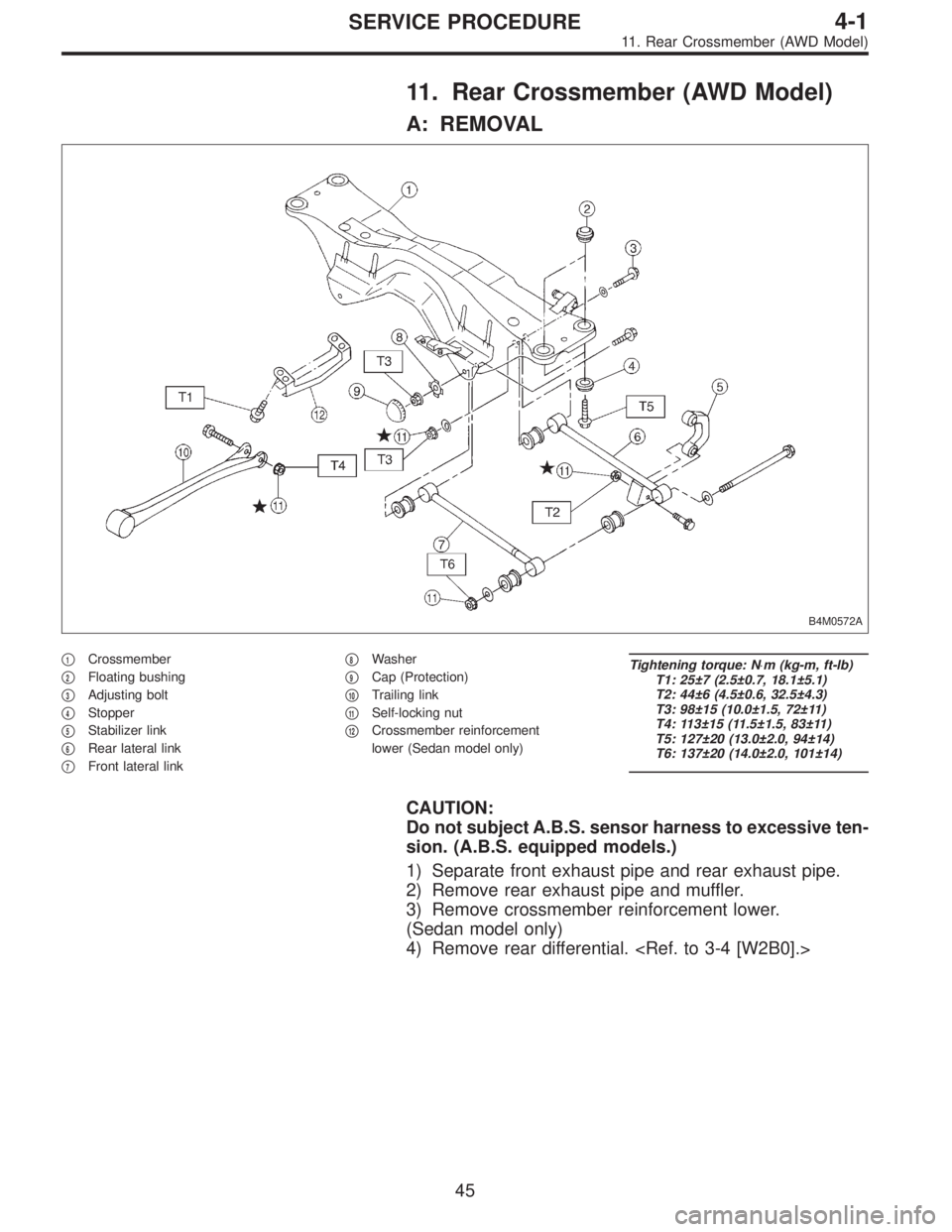
11. Rear Crossmember (AWD Model)
A: REMOVAL
B4M0572A
�1Crossmember
�
2Floating bushing
�
3Adjusting bolt
�
4Stopper
�
5Stabilizer link
�
6Rear lateral link
�
7Front lateral link�
8Washer
�
9Cap (Protection)
�
10Trailing link
�
11Self-locking nut
�
12Crossmember reinforcement
lower (Sedan model only)
Tightening torque: N⋅m (kg-m, ft-lb)
T1: 25±7 (2.5±0.7, 18.1±5.1)
T2: 44±6 (4.5±0.6, 32.5±4.3)
T3: 98±15 (10.0±1.5, 72±11)
T4: 113±15 (11.5±1.5, 83±11)
T5: 127±20 (13.0±2.0, 94±14)
T6: 137±20 (14.0±2.0, 101±14)
CAUTION:
Do not subject A.B.S. sensor harness to excessive ten-
sion. (A.B.S. equipped models.)
1) Separate front exhaust pipe and rear exhaust pipe.
2) Remove rear exhaust pipe and muffler.
3) Remove crossmember reinforcement lower.
(Sedan model only)
4) Remove rear differential.
45
4-1SERVICE PROCEDURE
11. Rear Crossmember (AWD Model)
Page 1135 of 3342
G4M0217
9) Remove disc rotor from hub.
If disc rotor seizes up within hub, drive disc rotor out by
installing an 8-mm bolt in screw hole on the rotor.
G4M0218
10) Remove cotter pin and castle nut which secure tie-rod
end to housing knuckle arm.
G4M0219
11) Using a puller, remove tie-rod ball joint from knuckle
arm.
G4M0220
12) On A.B.S. equipped models, remove A.B.S. sensor
assembly and harness in advance.
CAUTION:
Be sure to use soft jaws (such as aluminum plates)
when placing the mating surfaces of housing and strut
in a vise.
G4M0221
13) Remove transverse link ball joint from housing.
10
4-2SERVICE PROCEDURE
1. Front Axle
Page 1140 of 3342
 Install transverse link ball joint to housing.
Tightening torque:
44±6 N⋅m (4.5±0.6 kg-m, 32.5±4.3 ft-lb)
2) While aligning alignment mark on camber adjusting bolt
head, connec")
E: INSTALLATION
1) Install transverse link ball joint to housing.
Tightening torque:
44±6 N⋅m (4.5±0.6 kg-m, 32.5±4.3 ft-lb)
2) While aligning alignment mark on camber adjusting bolt
head, connect housing and strut.
CAUTION:
Use a new self-locking nut.
Tightening torque:
147±15 N⋅m (15±1.5 kg-m, 108±11 ft-lb)
3) Install speed sensor and harness on housing (only
vehicle equipped with A.B.S.).
4) Install disc rotor on hub.
5) Install disc brake caliper on housing.
Tightening torque:
59±10 N⋅m (6±1 kg-m, 43±7 ft-lb)
6) Install front drive shaft.
7) Connect stabilizer link.
G4M0236
8) Install tie-rod end ball joint on housing knuckle arm.
Tightening torque:
27.0±2.5 N⋅m (2.75±0.25 kg-m, 19.9±1.8 ft-lb)
G4M0237
9) While depressing brake pedal, tighten axle nut and lock
it securely.
Tightening torque:
186±20 N⋅m (19±2 kg-m, 137±14 ft-lb)
CAUTION:
�Use a new axle nut.
�Always tighten axle nut before installing wheel on
vehicle. If wheel is installed and comes in contact with
ground when axle nut is loose, wheel bearings may be
damaged.
�Be sure to tighten axle nut to specified torque. Do
not overtighten it as this may damage wheel bearing.
15
4-2SERVICE PROCEDURE
1. Front Axle
Page 1144 of 3342
G4M0246
12) Remove bolts which secure trailing link assembly to
rear housing.
CAUTION:
Discard old self-locking nut. Replace with a new one.
G4M0245
13) Remove bolts which secure lateral link assembly to
rear housing.
CAUTION:
Discard old self-locking nut. Replace with a new one.
G4M0247
14) Disengage BJ from housing splines, and remove rear
drive shaft assembly. If it is hard to remove, use STs.
ST1 926470000 AXLE SHAFT PULLER
ST2 927140000 PLATE
CAUTION:
�Be careful not to damage oil seal lip when removing
rear drive shaft.
�When rear drive shaft is to be replaced, also replace
inner oil seal with a new one.
G4M0248
15) Remove rear A.B.S. sensor from back plate (only
vehicle equipped with A.B.S.).
G4M0249
16) Remove bolts which secure rear housing to strut, and
separate the two.
18
4-2SERVICE PROCEDURE
2. Rear Axle (AWD Model)
Page 1148 of 3342
E: INSTALLATION
1) Connect rear housing assembly and strut assembly.
CAUTION:
Use a new self-locking nut.
Tightening torque:
147±15 N⋅m (15±1.5 kg-m, 108±11 ft-lb)
2) Fit BJ (bell joint) to rear housing splines.
CAUTION:
Be careful not to damage inner oil seal lip.
G4M0245
3) Connect rear housing assembly to lateral link assembly.
CAUTION:
Use a new self-locking nut.
Tightening torque:
137±20 N⋅m (14±2 kg-m, 101±14 ft-lb)
G4M0246
4) Connect rear housing assembly to trailing link assem-
bly.
CAUTION:
Use a new self-locking nut.
Tightening torque:
98—127 N⋅m (10—13 kg-m, 72—94 ft-lb)
5) Connect parking brake cable to parking brake.
Disc brake: Perform steps 6) through 8).
6) Install disc rotor on rear housing assembly.
G4M0240
7) Install disc brake caliper on back plate.
Tightening torque:
52±6 N⋅m (5.3±0.6 kg-m, 38.3±4.3 ft-lb)
G4M0266
8) Install rear speed sensor to back plate (only vehicle
equipped with A.B.S.).
22
4-2SERVICE PROCEDURE
2. Rear Axle (AWD Model)
Page 1156 of 3342
 Remove front drive shaft assembly. If it is hard to
remove, use ST1 and ST2.
ST1 926470000 AXLE SHAFT PULLER
ST2 927140000 PLATE
CAUTION:
�Be careful not to damage oil seal lip when removin")
G4M0216
8) Remove front drive shaft assembly. If it is hard to
remove, use ST1 and ST2.
ST1 926470000 AXLE SHAFT PULLER
ST2 927140000 PLATE
CAUTION:
�Be careful not to damage oil seal lip when removing
front drive shaft.
�When front drive shaft is to be replaced, also replace
inner oil seal.
2. REAR DRIVE SHAFT
1) Disconnect ground cable from battery.
2) Lift-up vehicle, and remove rear wheel cap and wheels.
CAUTION:
Be sure to loosen and retighten axle nut after remov-
ing wheel from vehicle. Failure to follow this rule may
damage wheel bearings.
3) Unlock axle nut.
4) Loosen axle nut using a socket wrench.
CAUTION:
Do not remove axle nut.
5) Remove A.B.S. sensor clamps and parking brake cable
bracket.
6) Remove bolts which secure lateral link assembly to rear
housing.
CAUTION:
Discard old self-locking nut. Replace with a new one.
7) Remove bolts which secure trailing link assembly to
rear housing.
CAUTION:
Discard old self-locking nut. Replace with a new one.
8) Remove crossmember reinforcement lower from cross-
member (4 door model only).
G4M0994
9) Remove DOJ from rear differential using ST.
ST 28099PA100 DRIVE SHAFT REMOVER
CAUTION:
Do not remove circlip attached to inside of differential.
29
4-2SERVICE PROCEDURE
4. Front and Rear Drive Shafts
 Remove disc rotor from hub.
If disc rotor seizes up within hub, drive disc rotor out by
installing an 8-mm bolt in screw hole on the rotor.
G4M0218
10) Remove cotter pin and castle nut whic")
 Remove bolts which secure trailing link assembly to
rear housing.
CAUTION:
Discard old self-locking nut. Replace with a new one.
G4M0245
13) Remove bolts which secure lateral link assembly")
 Connect rear housing assembly and strut assembly.
CAUTION:
Use a new self-locking nut.
Tightening torque:
147±15 N⋅m (15±1.5 kg-m, 108±11 ft-lb)
2) Fit BJ (bell joint) to rear")