Page 1376 of 3342
B4M0918A
: Is the indicated reading 0.7±0.2 V when G
sensor is inclined backwards to 90°?
: G sensor is normal.
: Replace G sensor.
92
4-4SERVICE PROCEDURE
17. G Sensor for ABS System (ABS 5.3 Type)
Page 1415 of 3342
B4M1222
E: INSTALLATION
1) Install ABSCM&H/U.
CAUTION:
Confirm that the specifications of the ABSCM&H/U
conforms to the vehicle specifications.
Tightening torque:
18±5 N⋅m (1.8±0.5 kg-m, 13.0±3.6 ft-lb)
2) Connect brake pipes to their correct ABSCM&H/U con-
nections.
3) Using cable clip, secure ABSCM&H/U harness to
bracket.
4) Connect connector to ABSCM&H/U.
CAUTION:
�Be sure to remove all foreign matter from inside the
connector before connecting.
�Ensure that the ABSCM&H/U connector is securely
locked.
5) Install air intake duct.
6) Connect ground cable to battery.
7) Bleed air from the brake system.
23. ABS Sensor (ABS 5.3i Type)
24. G Sensor (ABS 5.3i Type)
130
4-4SERVICE PROCEDURE
22. ABS Control Module and Hydraulic Control Unit (ABSCM&H/U) (ABS 5.3i Type) - 24. G Sensor (ABS 5.3i Type)
Page 1416 of 3342
B4M1222
E: INSTALLATION
1) Install ABSCM&H/U.
CAUTION:
Confirm that the specifications of the ABSCM&H/U
conforms to the vehicle specifications.
Tightening torque:
18±5 N⋅m (1.8±0.5 kg-m, 13.0±3.6 ft-lb)
2) Connect brake pipes to their correct ABSCM&H/U con-
nections.
3) Using cable clip, secure ABSCM&H/U harness to
bracket.
4) Connect connector to ABSCM&H/U.
CAUTION:
�Be sure to remove all foreign matter from inside the
connector before connecting.
�Ensure that the ABSCM&H/U connector is securely
locked.
5) Install air intake duct.
6) Connect ground cable to battery.
7) Bleed air from the brake system.
23. ABS Sensor (ABS 5.3i Type)
24. G Sensor (ABS 5.3i Type)
130
4-4SERVICE PROCEDURE
22. ABS Control Module and Hydraulic Control Unit (ABSCM&H/U) (ABS 5.3i Type) - 24. G Sensor (ABS 5.3i Type)
Page 1417 of 3342
B4M1222
E: INSTALLATION
1) Install ABSCM&H/U.
CAUTION:
Confirm that the specifications of the ABSCM&H/U
conforms to the vehicle specifications.
Tightening torque:
18±5 N⋅m (1.8±0.5 kg-m, 13.0±3.6 ft-lb)
2) Connect brake pipes to their correct ABSCM&H/U con-
nections.
3) Using cable clip, secure ABSCM&H/U harness to
bracket.
4) Connect connector to ABSCM&H/U.
CAUTION:
�Be sure to remove all foreign matter from inside the
connector before connecting.
�Ensure that the ABSCM&H/U connector is securely
locked.
5) Install air intake duct.
6) Connect ground cable to battery.
7) Bleed air from the brake system.
23. ABS Sensor (ABS 5.3i Type)
24. G Sensor (ABS 5.3i Type)
130
4-4SERVICE PROCEDURE
22. ABS Control Module and Hydraulic Control Unit (ABSCM&H/U) (ABS 5.3i Type) - 24. G Sensor (ABS 5.3i Type)
Page 1422 of 3342
1. Pedal (MT Model)
1. 2200 cc MODEL
B4M0737A
�1Accelerator pedal
�
2Bushing
�
3Holder
�
4Accelerator bracket
�
5Stopper
�
6Clip
�
7Accelerator spring
�
8Accelerator pedal spring
�
9Spring pin
�
10Accelerator pedal pad
�
11Accelerator stopper
�
12Clip
�
13Accelerator plate�
14Pedal bracket
�
15Stop light switch (Without T.C.S.) /
stroke sensor (With T.C.S.)
�
16Brake pedal
�
17Spacer
�
18Snap pin
�
19Brake pedal pad
�
20Clevis pin
�
21Brake pedal spring
�
22Washer
�
23Clutch pedal pad
�
24Clutch pedal
�
25Bushing assist�
26Spring assist
�
27Clutch cable clamp
�
28Clutch cable
�
29Mass damper
�
30Clutch switch (Starter interlock)
�
31Clutch switch (With cruise control)
Tightening torque: N⋅m (kg-m, ft-lb)
T1: 5.9±1.5 (0.60±0.15, 4.3±1.1)
T2: 8±2 (0.8±0.2, 5.8±1.4)
T3: 18±5 (1.8±0.5, 13.0±3.6)
T4: 29±7 (3.0±0.7, 21.7±5.1)
3
4-5COMPONENT PARTS
1. Pedal (MT Model)
Page 1424 of 3342
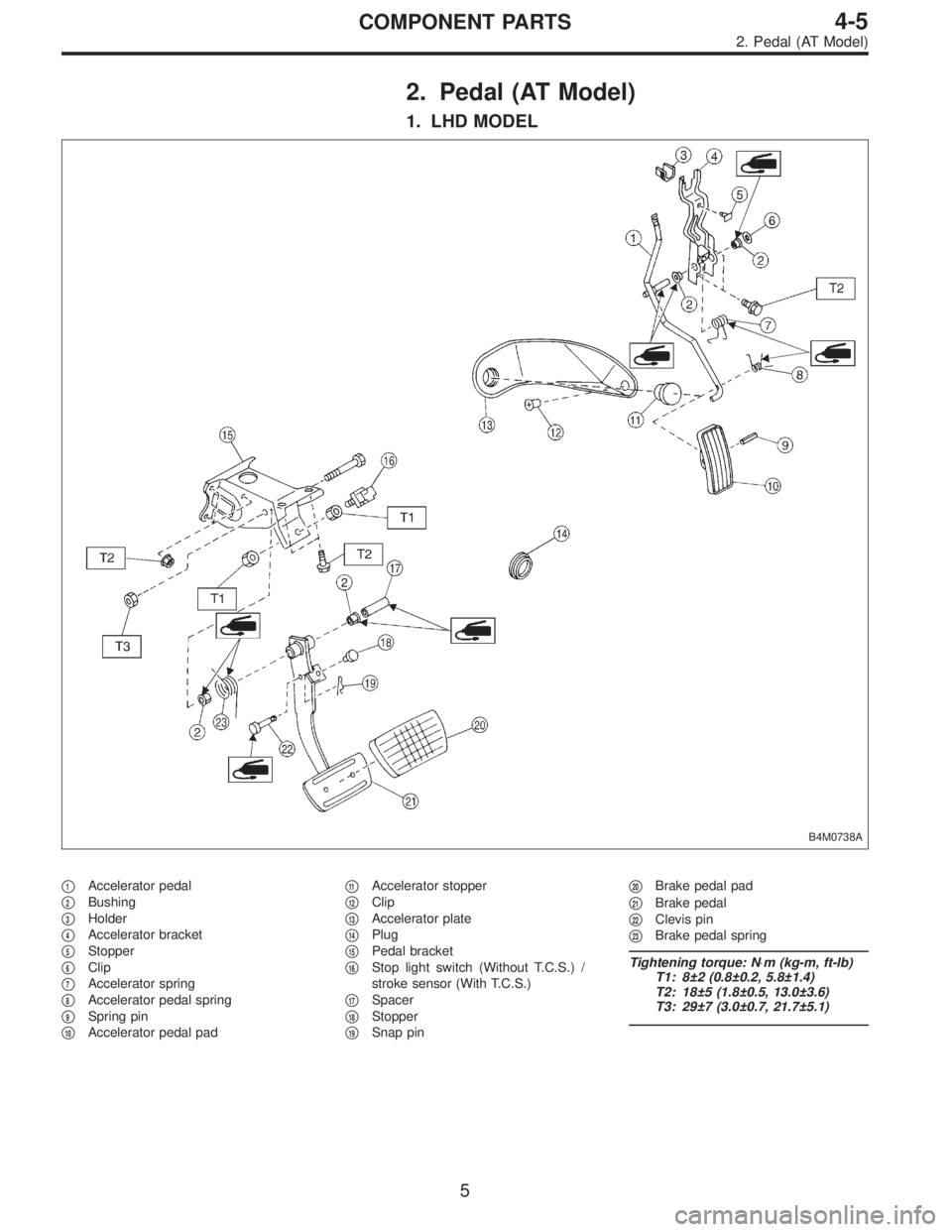
2. Pedal (AT Model)
1. LHD MODEL
B4M0738A
�1Accelerator pedal
�
2Bushing
�
3Holder
�
4Accelerator bracket
�
5Stopper
�
6Clip
�
7Accelerator spring
�
8Accelerator pedal spring
�
9Spring pin
�
10Accelerator pedal pad�
11Accelerator stopper
�
12Clip
�
13Accelerator plate
�
14Plug
�
15Pedal bracket
�
16Stop light switch (Without T.C.S.) /
stroke sensor (With T.C.S.)
�
17Spacer
�
18Stopper
�
19Snap pin�
20Brake pedal pad
�
21Brake pedal
�
22Clevis pin
�
23Brake pedal spring
Tightening torque: N⋅m (kg-m, ft-lb)
T1: 8±2 (0.8±0.2, 5.8±1.4)
T2: 18±5 (1.8±0.5, 13.0±3.6)
T3: 29±7 (3.0±0.7, 21.7±5.1)
5
4-5COMPONENT PARTS
2. Pedal (AT Model)
Page 1637 of 3342

2. WAGON MODEL
Installation is in the reverse order of removal.
CAUTION:
�Do not allow center seat belt to get under cushion
when folding cushion.
�Ensure that side seat belt tongue is free from cush-
ion and trim panel.
�Lift front of cushion to ensure that cushion is prop-
erly locked.
B5M0038A
3. Front Seat Belt
A: REMOVAL AND INSTALLATION
1. OUTER BELT
1) Remove through anchor cover cap.
2) Remove shoulder anchor bolt.
3) Remove side sill rear upper cover and front pillar lower
trim.
4) Remove center pillar lower trim.
B5M0039
5) Remove webbing guide.
6) Roll up floor mat at the bottom of center pillar.
7) Remove lap anchor bolt.
8) Remove outer belt assembly.
G5M0356
2. INNER BELT
Remove anchor nut.
G5M0357
3. ADJUSTABLE SHOULDER ANCHOR
1) Remove shoulder anchor bolt.
2) Remove lower center pillar trim.
3) Remove front and center pillar upper trim.
4) Remove adjustable shoulder anchor assembly.
5) Installation is in the reverse order of removal.
CAUTION:
�The left and right ELR’s are not mutually inter-
changeable because different sensors are used.
�Be careful not to twist belts during installation.
11
5-3SERVICE PROCEDURE
2. Rear Seat - 3. Front Seat Belt
Page 1638 of 3342

2. WAGON MODEL
Installation is in the reverse order of removal.
CAUTION:
�Do not allow center seat belt to get under cushion
when folding cushion.
�Ensure that side seat belt tongue is free from cush-
ion and trim panel.
�Lift front of cushion to ensure that cushion is prop-
erly locked.
B5M0038A
3. Front Seat Belt
A: REMOVAL AND INSTALLATION
1. OUTER BELT
1) Remove through anchor cover cap.
2) Remove shoulder anchor bolt.
3) Remove side sill rear upper cover and front pillar lower
trim.
4) Remove center pillar lower trim.
B5M0039
5) Remove webbing guide.
6) Roll up floor mat at the bottom of center pillar.
7) Remove lap anchor bolt.
8) Remove outer belt assembly.
G5M0356
2. INNER BELT
Remove anchor nut.
G5M0357
3. ADJUSTABLE SHOULDER ANCHOR
1) Remove shoulder anchor bolt.
2) Remove lower center pillar trim.
3) Remove front and center pillar upper trim.
4) Remove adjustable shoulder anchor assembly.
5) Installation is in the reverse order of removal.
CAUTION:
�The left and right ELR’s are not mutually inter-
changeable because different sensors are used.
�Be careful not to twist belts during installation.
11
5-3SERVICE PROCEDURE
2. Rear Seat - 3. Front Seat Belt
")
 Install ABSCM&H/U.
CAUTION:
Confirm that the specifications of the ABSCM&H/U
conforms to the vehicle specifications.
Tightening torque:
18±5 N⋅m (1.8±0.5 kg-m, 13.0±3.6")
 Install ABSCM&H/U.
CAUTION:
Confirm that the specifications of the ABSCM&H/U
conforms to the vehicle specifications.
Tightening torque:
18±5 N⋅m (1.8±0.5 kg-m, 13.0±3.6")
 Install ABSCM&H/U.
CAUTION:
Confirm that the specifications of the ABSCM&H/U
conforms to the vehicle specifications.
Tightening torque:
18±5 N⋅m (1.8±0.5 kg-m, 13.0±3.6")