Page 931 of 3342
G3M0856
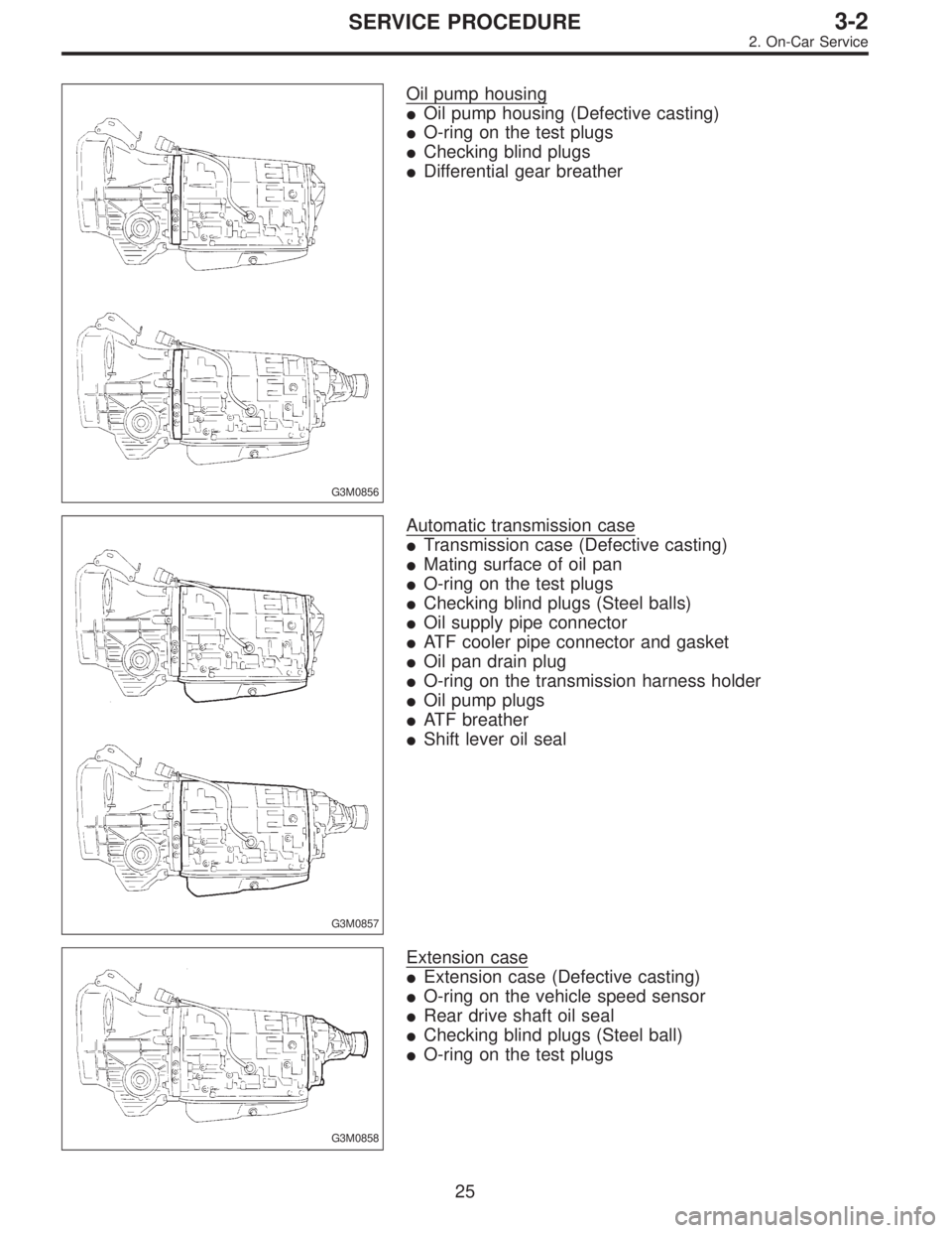
Oil pump housing
�Oil pump housing (Defective casting)
�O-ring on the test plugs
�Checking blind plugs
�Differential gear breather
G3M0857
Automatic transmission case
�Transmission case (Defective casting)
�Mating surface of oil pan
�O-ring on the test plugs
�Checking blind plugs (Steel balls)
�Oil supply pipe connector
�ATF cooler pipe connector and gasket
�Oil pan drain plug
�O-ring on the transmission harness holder
�Oil pump plugs
�ATF breather
�Shift lever oil seal
G3M0858
Extension case
�Extension case (Defective casting)
�O-ring on the vehicle speed sensor
�Rear drive shaft oil seal
�Checking blind plugs (Steel ball)
�O-ring on the test plugs
25
3-2SERVICE PROCEDURE
2. On-Car Service
Page 935 of 3342
G3M0293
(4) Check if there is continuity at equal points when the
select lever is turned 1.5°in both directions from the N
range.
If there is continuity in one direction and the continuity
in the other or if there is continuity at unequal points,
adjust the inhibitor switch.
G3M0294
(1) Loosen the three inhibitor switch securing bolts.
(2) Shift the select lever to the N range.
(3) Insert ST as vertical as possible into the holes in
the inhibitor switch lever and switch body.
ST 499267300 STOPPER PIN
(4) Tighten the three inhibitor switch bolts.
Tightening torque:
3.4±0.5 N⋅m (0.35±0.05 kg-m, 2.5±0.4 ft-lb)
(5) Repeat the above checks. If the inhibitor switch is
determined to be“faulty”, replace it.
G3M0295
3. SENSOR (IN TRANSMISSION)
Check each sensor, solenoid and ground system for short
circuits.
29
3-2SERVICE PROCEDURE
2. On-Car Service
Page 936 of 3342
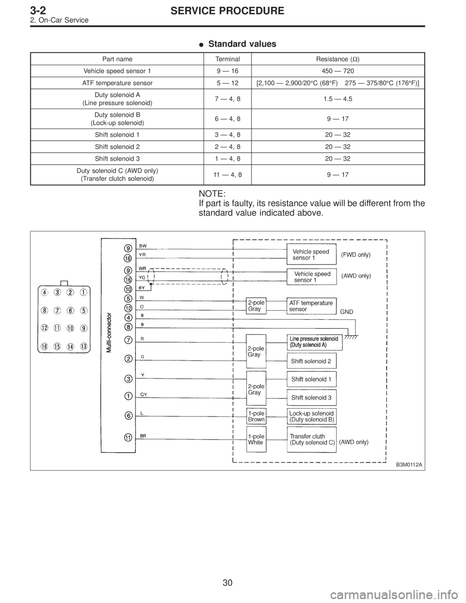
�Standard values
Part name Terminal Resistance (Ω)
Vehicle speed sensor 1 9—16 450—720
ATF temperature sensor 5—12 [2,100—2,900/20°C (68°F) 275—375/80°C (176°F)]
Duty solenoid A
(Line pressure solenoid)7—4, 8 1.5—4.5
Duty solenoid B
(Lock-up solenoid)6—4, 8 9—17
Shift solenoid 1 3—4, 8 20—32
Shift solenoid 2 2—4, 8 20—32
Shift solenoid 3 1—4, 8 20—32
Duty solenoid C (AWD only)
(Transfer clutch solenoid)11—4, 8 9—17
NOTE:
If part is faulty, its resistance value will be different from the
standard value indicated above.
B3M0112A
30
3-2SERVICE PROCEDURE
2. On-Car Service
Page 940 of 3342
G3M0304
2. DUTY SOLENOID C AND TRANSFER VALVE BODY
1) Removal
(1) Remove pitching stopper.
G3M0297
(2) Raise vehicle and drain ATF.
G3M0305
(3) Remove front exhaust pipe.
Disconnect oxygen sensor connector, and remove
exhaust pipe.
G3M0782
(4) Remove propeller shaft.
NOTE:
Before removing propeller shaft, scribe matching marks on
propeller shaft and rear differential coupling.
G3M0306
(5) Remove rear crossmember.
�Support transmission using a transmission jack and
raise slightly.
�Remove bolts and nuts as shown in Figure.
34
3-2SERVICE PROCEDURE
2. On-Car Service
Page 941 of 3342
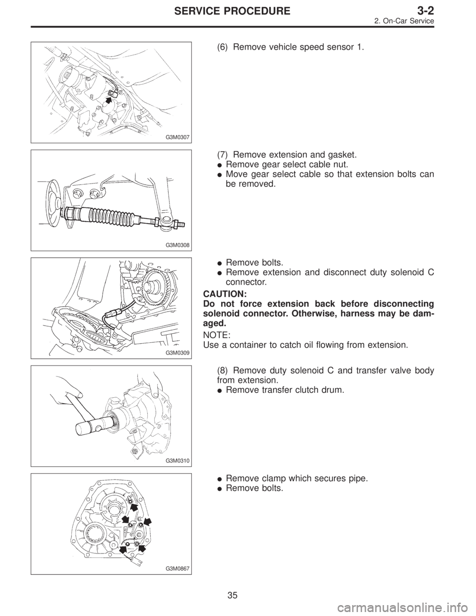
G3M0307
(6) Remove vehicle speed sensor 1.
G3M0308
(7) Remove extension and gasket.
�Remove gear select cable nut.
�Move gear select cable so that extension bolts can
be removed.
G3M0309
�Remove bolts.
�Remove extension and disconnect duty solenoid C
connector.
CAUTION:
Do not force extension back before disconnecting
solenoid connector. Otherwise, harness may be dam-
aged.
NOTE:
Use a container to catch oil flowing from extension.
G3M0310
(8) Remove duty solenoid C and transfer valve body
from extension.
�Remove transfer clutch drum.
G3M0867
�Remove clamp which secures pipe.
�Remove bolts.
35
3-2SERVICE PROCEDURE
2. On-Car Service
Page 942 of 3342
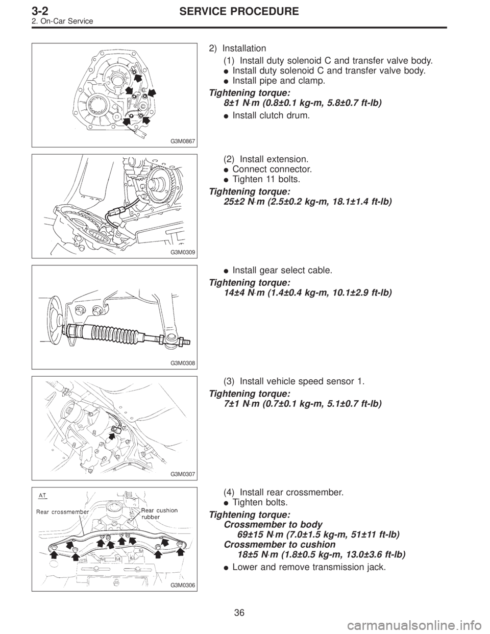
G3M0867
2) Installation
(1) Install duty solenoid C and transfer valve body.
�Install duty solenoid C and transfer valve body.
�Install pipe and clamp.
Tightening torque:
8±1 N⋅m (0.8±0.1 kg-m, 5.8±0.7 ft-lb)
�Install clutch drum.
G3M0309
(2) Install extension.
�Connect connector.
�Tighten 11 bolts.
Tightening torque:
25±2 N⋅m (2.5±0.2 kg-m, 18.1±1.4 ft-lb)
G3M0308
�Install gear select cable.
Tightening torque:
14±4 N⋅m (1.4±0.4 kg-m, 10.1±2.9 ft-lb)
G3M0307
(3) Install vehicle speed sensor 1.
Tightening torque:
7±1 N⋅m (0.7±0.1 kg-m, 5.1±0.7 ft-lb)
G3M0306
(4) Install rear crossmember.
�Tighten bolts.
Tightening torque:
Crossmember to body
69±15 N⋅m (7.0±1.5 kg-m, 51±11 ft-lb)
Crossmember to cushion
18±5 N⋅m (1.8±0.5 kg-m, 13.0±3.6 ft-lb)
�Lower and remove transmission jack.
36
3-2SERVICE PROCEDURE
2. On-Car Service
Page 943 of 3342
G3M0782
(5) Install propeller shaft.
Tightening torque:
At rear differential
23±5 N⋅m (2.3±0.5 kg-m, 16.6±3.6 ft-lb)
At center bearing
39±5 N⋅m (4.0±0.5 kg-m, 28.9±3.6 ft-lb)
NOTE:
Align matching marks on propeller shaft and rear differen-
tial coupling.
G3M0305
(6) Install front exhaust pipe
Tightening torque:
At engine
29±5 N⋅m (3.0±0.5 kg-m, 21.7±3.6 ft-lb)
At hanger
29±5 N⋅m (3.0±0.5 kg-m, 21.7±3.6 ft-lb)
At front and rear connections
18±5 N⋅m (1.8±0.5 kg-m, 13.0±3.6 ft-lb)
G3M0313
(7) Lower and remove jack.
(8) Connect the following parts:
�Oxygen sensor connector
�Multi-connector
G3M0304
(9) Install pitching stopper.
Tightening torque:
Body side
57±10 N⋅m (5.8±1.0 kg-m, 42±7 ft-lb)
Engine side
49±5 N⋅m (5.0±0.5 kg-m, 36.2±3.6 ft-lb)
G3M0282
(10) Replenish ATF and check oil level. Check for
leaks.
37
3-2SERVICE PROCEDURE
2. On-Car Service
Page 956 of 3342
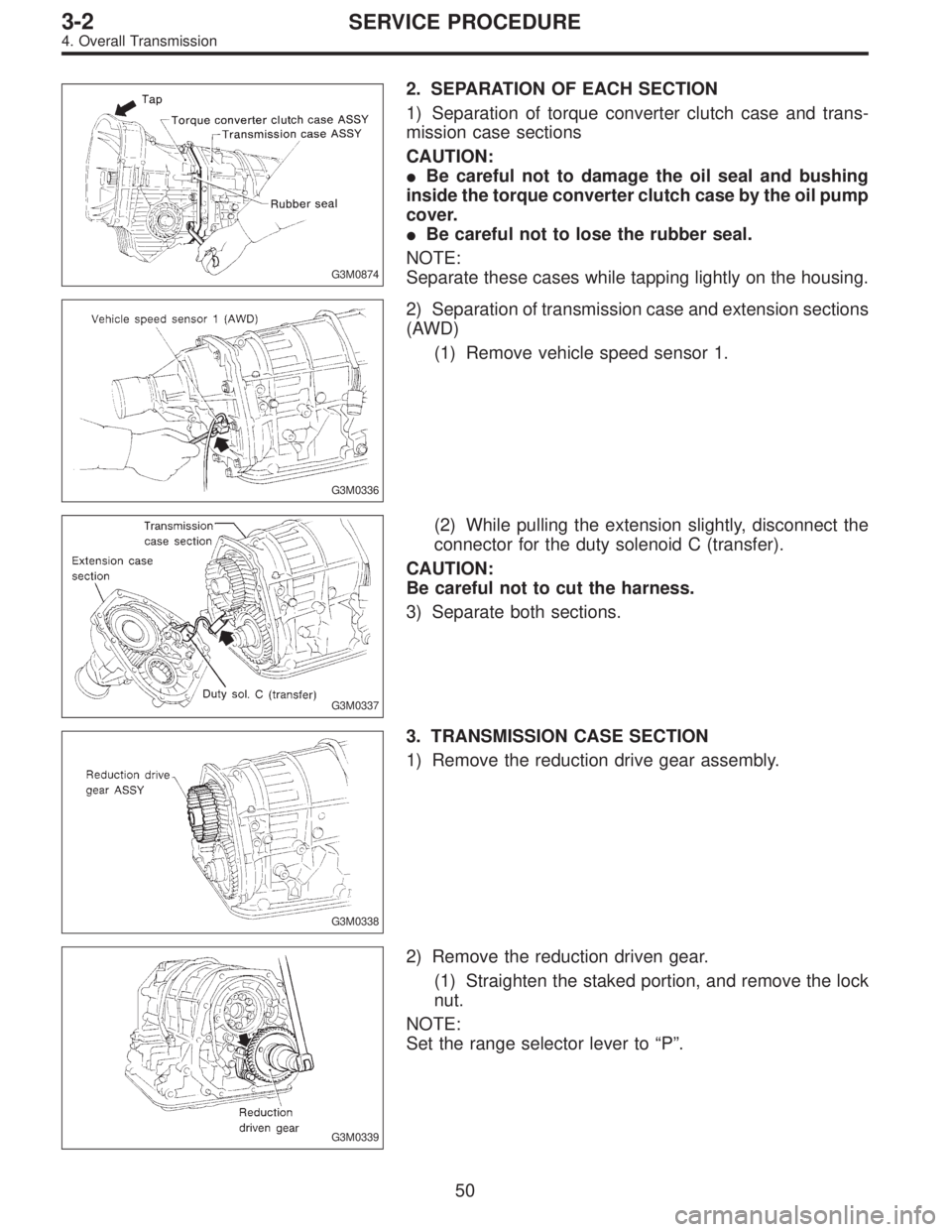
G3M0874
2. SEPARATION OF EACH SECTION
1) Separation of torque converter clutch case and trans-
mission case sections
CAUTION:
�Be careful not to damage the oil seal and bushing
inside the torque converter clutch case by the oil pump
cover.
�Be careful not to lose the rubber seal.
NOTE:
Separate these cases while tapping lightly on the housing.
G3M0336
2) Separation of transmission case and extension sections
(AWD)
(1) Remove vehicle speed sensor 1.
G3M0337
(2) While pulling the extension slightly, disconnect the
connector for the duty solenoid C (transfer).
CAUTION:
Be careful not to cut the harness.
3) Separate both sections.
G3M0338
3. TRANSMISSION CASE SECTION
1) Remove the reduction drive gear assembly.
G3M0339
2) Remove the reduction driven gear.
(1) Straighten the staked portion, and remove the lock
nut.
NOTE:
Set the range selector lever to“P”.
50
3-2SERVICE PROCEDURE
4. Overall Transmission
 Check if there is continuity at equal points when the
select lever is turned 1.5°in both directions from the N
range.
If there is continuity in one direction and the continuity
in the oth")
 Removal
(1) Remove pitching stopper.
G3M0297
(2) Raise vehicle and drain ATF.
G3M0305
(3) Remove front exhaust pipe.
Disconnect oxygen sensor conn")
 Install propeller shaft.
Tightening torque:
At rear differential
23±5 N⋅m (2.3±0.5 kg-m, 16.6±3.6 ft-lb)
At center bearing
39±5 N⋅m (4.0±0.5 kg-m, 28.9±3.6 ft-lb)
NOTE:
Align mat")