Page 429 of 3342
B2M0724
2. Oil Pan and Oil Strainer
A: REMOVAL
1) Remove front wheels.
2) Remove air intake duct.
3) Disconnect connector from front oxygen sensor.
B2M0725
4) Disconnect connector from rear oxygen sensor. (Cali-
fornia 2200 cc model only)
G2M0295
5) Remove pitching stopper.
B2M0320
6) Remove radiator upper brackets.
B2M0053
7) Support engine with a lifting device and wire ropes.
8) Lift-up the vehicle.
CAUTION:
At this time, raise up wire ropes.
9
2-4SERVICE PROCEDURE
2. Oil Pan and Oil Strainer
Page 430 of 3342
G2M0066
9) Drain engine oil.
Set container under the vehicle, and remove drain plug
from oil pan.
B2M0312
10) Disconnect connector from rear oxygen sensor.
(Except California 2200 cc model)
B2M0054
11) Remove front exhaust pipe.
(1) Separate front catalytic converter from center
exhaust pipe.
(2) Remove front exhaust pipe from engine.
(3) Remove bolt which installs front exhaust pipe on
bracket.
B2M0743A
12) Remove nuts which install front cushion rubber onto
front crossmember.
G2M0081
13) Remove bolts which install oil pan on cylinder block
while raising up engine.
14) Insert oil pan cutter blade between cylinder block-to-oil
pan clearance.
CAUTION:
Do not use a screwdriver or similar tool in place of oil
pan cutter.
10
2-4SERVICE PROCEDURE
2. Oil Pan and Oil Strainer
Page 433 of 3342
B2M0054
9) Install front exhaust pipe.
CAUTION:
Always use the new gaskets.
(1) Place front exhaust pipe on bracket.
(2) Tighten nuts which install front exhaust pipe on
engine.
Tightening torque:
30±5 N⋅m (3.1±0.5 kg-m, 22.4±3.6 ft-lb)
B2M0055
(3) Tighten nuts which install front catalytic converter to
center exhaust pipe.
Tightening torque:
35±5 N⋅m (3.6±0.5 kg-m, 26.0±3.6 ft-lb)
B2M0056
(4) Tighten bolt which installs front exhaust pipe on
bracket.
Tightening torque:
24±3 N⋅m (2.4±0.3 kg-m, 17.4±2.2 ft-lb)
B2M0312
10) Connect connector to rear oxygen sensor. (Except
California 2200 cc model)
B2M0053
11) Lower the vehicle.
CAUTION:
At this time, lower lifting device and release steel
cables.
12) Remove lifting device and steel cables.
13
2-4SERVICE PROCEDURE
2. Oil Pan and Oil Strainer
Page 434 of 3342
B2M0724
13) Connect connector to front oxygen sensor.
B2M0725
14) Connect connector to rear oxygen sensor. (California
2200 cc model only)
G2M0302
15) Install pitching stopper.
Tightening torque:
T1: 49±5 N⋅m (5.0±0.5 kg-m, 36.2±3.6 ft-lb)
T2: 57±10 N⋅m (5.8±1.0 kg-m, 42±7 ft-lb)
B2M0320
16) Install radiator upper brackets.
Tightening torque:
12±3 N⋅m (1.2±0.3 kg-m, 8.7±2.2 ft-lb)
B2M0321
17) Install air intake duct.
18) Fill engine oil through filler pipe up to upper point of
level gauge.
Engine oil capacity:
2200 cc ; Upper level
4.0�(4.2 US qt, 3.5 Imp qt)
Lower level
3.0�(3.2 US qt, 2.6 Imp qt)
2500 cc ; Upper level
4.5�(4.8 US qt, 4.0 Imp qt)
14
2-4SERVICE PROCEDURE
2. Oil Pan and Oil Strainer
Page 443 of 3342
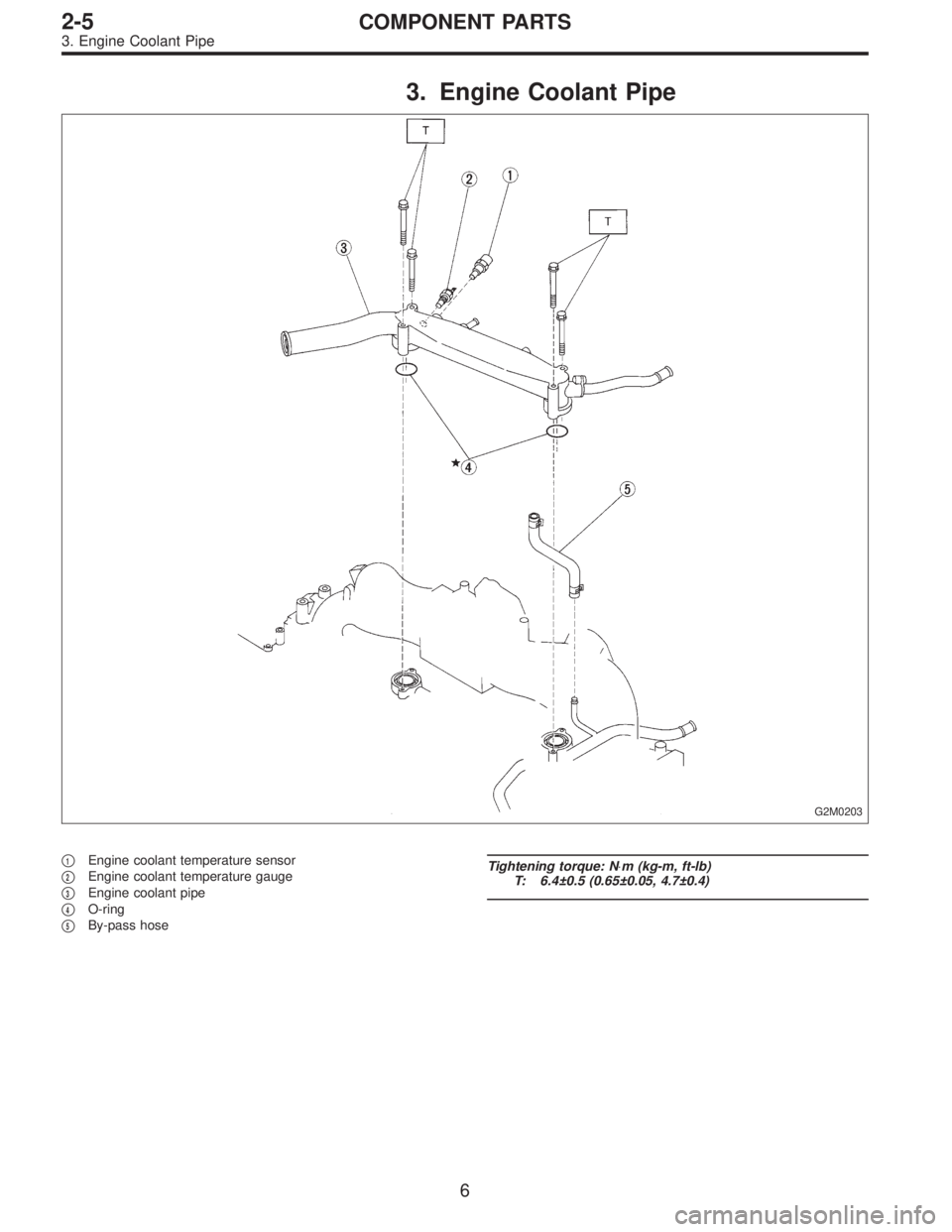
3. Engine Coolant Pipe
G2M0203
�1Engine coolant temperature sensor
�
2Engine coolant temperature gauge
�
3Engine coolant pipe
�
4O-ring
�
5By-pass hose
Tightening torque: N⋅m (kg-m, ft-lb)
T: 6.4±0.5 (0.65±0.05, 4.7±0.4)
6
2-5COMPONENT PARTS
3. Engine Coolant Pipe
Page 447 of 3342
B2M0302
7) Remove timing belt.
B2M0303
8) Remove belt tension adjuster.
G2M0417
9) Remove camshaft position sensor.
G2M0207
10) Remove left side camshaft pulley by using ST.
ST 499207100 CAMSHAFT SPROCKET WRENCH
G2M0208
11) Remove left side rear timing belt cover.
10
2-5SERVICE PROCEDURE
2. Engine Coolant Pump
Page 460 of 3342

1. Engine Cooling System
Trouble Possible cause Corrective action
Over-heatinga. Insufficient engine coolantReplenish engine coolant, inspect for leakage, and
repair.
b. Loose timing belt Repair or replace timing belt tensioner.
c. Oil on drive belt Replace.
d. Malfunction of thermostat Replace.
e. Malfunction of engine coolant pump Replace.
f. Clogged engine coolant passage Clean.
g. Improper ignition timingInspect and repair ignition control system.
h. Clogged or leaking radiator Clean or repair, or replace.
i. Improper engine oil in engine coolant Replace engine coolant.
j. Air/fuel mixture ratio too leanInspect and repair fuel injection system.
k. Excessive back pressure in exhaust system Clean or replace.
l. Insufficient clearance between piston and cylinder Adjust or replace.
m. Slipping clutch Repair or replace.
n. Dragging brake Adjust.
o. Improper transmission oil Replace.
p. Defective thermostat Replace.
q. Malfunction of electric fanInspect radiator fan relay, engine coolant temperature
sensor or radiator motor and replace there.
Over-coolinga. Atmospheric temperature extremely low Partly cover radiator front area.
b. Defective thermostat Replace.
Engine coolant
leaks.a. Loosened or damaged connecting units on hoses Repair or replace.
b. Leakage from engine coolant pump Replace.
c. Leakage from engine coolant pipe Repair or replace.
d. Leakage around cylinder head gasket Retighten cylinder head bolts or replace gasket.
e. Damaged or cracked cylinder head and crankcase Repair or replace.
f. Damaged or cracked thermostat case Repair or replace.
g. Leakage from radiator Repair or replace.
Noisea. Defective drive belt Replace.
b. Defective radiator fan Replace.
c. Defective engine coolant pump bearing Replace engine coolant pump.
d. Defective engine coolant pump mechanical seal Replace engine coolant pump.
20
2-5DIAGNOSTICS
1. Engine Cooling System
Page 471 of 3342

�1Intake manifold gasket LH
�
2Intake manifold gasket RH
�
3Fuel injector pipe insulator
�
4Fuel injector pipe
�
5O-ring A
�
6O-ring B
�
7Fuel injector
�
8Insulator
�
9Fuel injector cap
�
10Plate
�
11Sealing
�
12Gasket
�
13Engine coolant hose B
�
14Air by-pass hose
�
15Idle air control solenoid valve
�
16Engine coolant hose A
�
17Nipple (AT model)
�
18Plug
�
19PCV valve
�
20Purge control solenoid valve
�
21Nipple
�
22BPT (Except 2200 cc MT model)
�
23BPT holder bracket (Except 2200 cc MT model)
�
24Back pressure hose (Except 2200 cc MT model)
�
25EGR vacuum hose A (Except 2200 cc MT model)�
26EGR vacuum hose B (Except 2200 cc MT model)
�
27EGR valve (Except 2200 cc MT model)
�
28Gasket (Except 2200 cc MT model)
�
29EGR solenoid valve (Except 2200 cc MT model)
�
30EGR pipe (Except 2200 cc MT model)
�
31Pressure sensor
�
32Pressure sources switching solenoid valve
�
33Vacuum hose A
�
34Vacuum hose B
�
35Vacuum hose C
�
36Bracket (Except Canada spec. vehicles)
�
37Bracket (For Canada spec. vehicles)
�
38Intake manifold
Tightening torque: N⋅m (kg-m, ft-lb)
T1: 3.4±0.5 (0.35±0.05, 2.5±0.4)
T2: 4.9±0.5 (0.5±0.05, 3.6±0.4)
T3: 6.4±0.5 (0.65±0.05, 4.7±0.4)
T4: 16±1.5 (1.6±0.15, 11.6±1.1)
T5: 19±1.5 (1.9±0.15, 13.7±1.1)
T6: 19±2 (1.9±0.2, 13.7±1.4)
T7: 23±3 (2.3±0.3, 16.6±2.2)
T8: 25±2 (2.5±0.2, 18.1±1.4)
T9: 34±2 (3.5±0.2, 25.3±1.4)
3
2-7COMPONENT PARTS
1. Intake Manifold
 Remove front wheels.
2) Remove air intake duct.
3) Disconnect connector from front oxygen sensor.
B2M0725
4) Disconnect connector from rear oxygen sen")
 Drain engine oil.
Set container under the vehicle, and remove drain plug
from oil pan.
B2M0312
10) Disconnect connector from rear oxygen sensor.
(Except California 2200 cc model)
B2M0054
11")
 Install front exhaust pipe.
CAUTION:
Always use the new gaskets.
(1) Place front exhaust pipe on bracket.
(2) Tighten nuts which install front exhaust pipe on
engine.
Tightening torque:
30�")
 Connect connector to front oxygen sensor.
B2M0725
14) Connect connector to rear oxygen sensor. (California
2200 cc model only)
G2M0302
15) Install pitching stopper.
Tightening torque:
T1:")
![SUBARU LEGACY 1997 Service Repair Manual B2M0302
7) Remove timing belt.
<Ref. to 1-5 [02A0].>
B2M0303
8) Remove belt tension adjuster.
G2M0417
9) Remove camshaft position sensor.
<Ref. to 2-7 [W10A0].>
G2M0207
10) Remove left side camshaft p](/manual-img/17/57434/w960_57434-446.png "SUBARU LEGACY 1997 Service Repair Manual B2M0302
7) Remove timing belt.
<Ref. to 1-5 [02A0].>
B2M0303
8) Remove belt tension adjuster.
G2M0417
9) Remove camshaft position sensor.
<Ref. to 2-7 [W10A0].>
G2M0207
10) Remove left side camshaft p")