Page 240 of 3342
B2M0960
3) Disconnect connector from fuel tank pressure sensor.
4) Remove bolts which install fuel tank pressure sensor
bracket on body.
B2M0961
5) Disconnect hose from fuel tank pressure sensor.
6) Remove fuel tank pressure sensor from bracket.
7) Installation is in the reverse order of removal.
G6M0095
10. Pressure Control Solenoid Valve
(2200 cc AWD Model)
A: REMOVAL AND INSTALLATION
1) Disconnect battery ground cable.
2) Lift-up the vehicle.
B2M0962
3) Disconnect evaporation hoses from pressure control
valve.
4) Disconnect connector from pressure control valve.
B2M0963
5) Remove pressure control valve from bracket.
6) Installation is in the reverse order of removal.
12
2-1SERVICE PROCEDURE
9. Fuel Tank Pressure Sensor (2200 cc AWD Model) - 10. Pressure Control Solenoid Valve (2200 cc AWD Model)
Page 243 of 3342
G6M0095
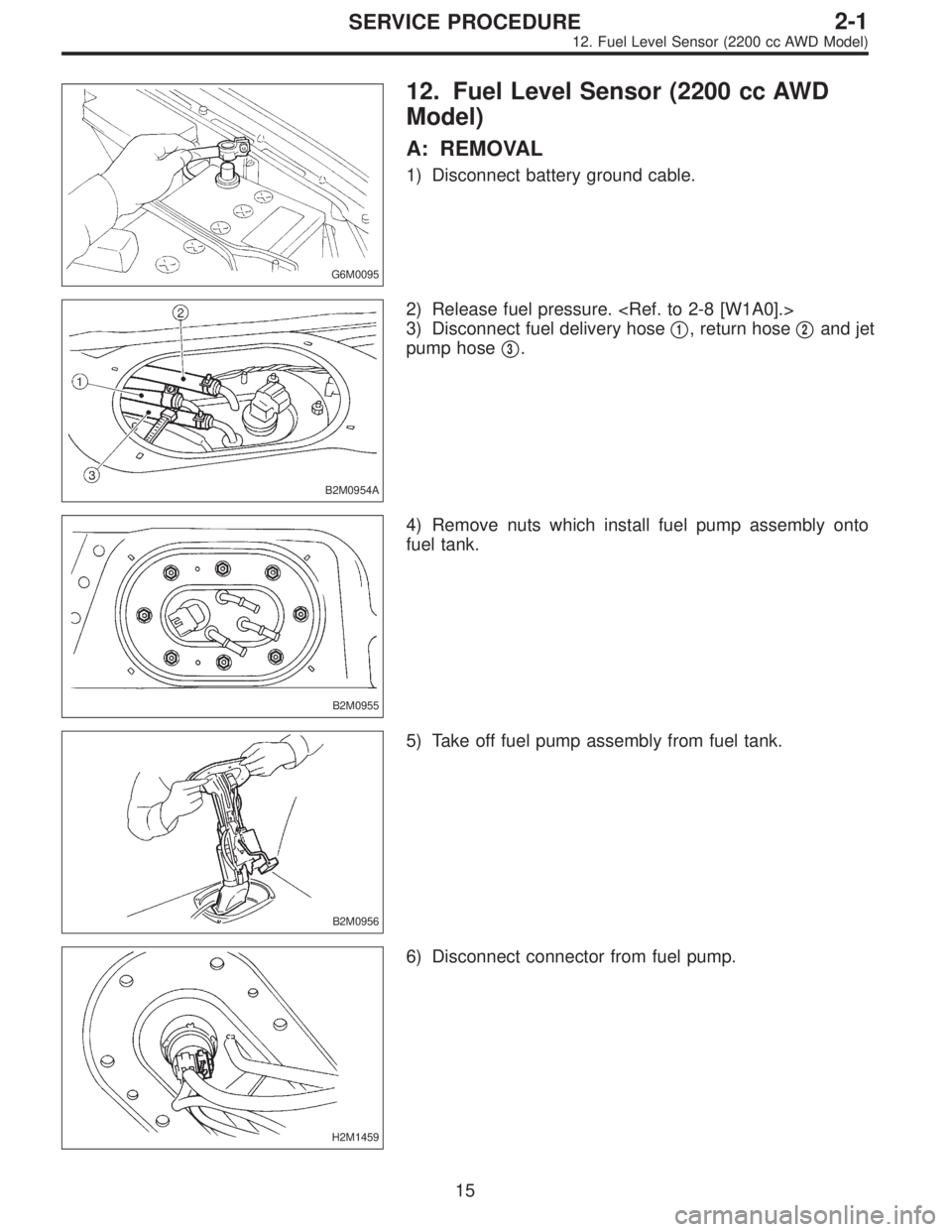
12. Fuel Level Sensor (2200 cc AWD
Model)
A: REMOVAL
1) Disconnect battery ground cable.
B2M0954A
2) Release fuel pressure.
3) Disconnect fuel delivery hose�
1, return hose�2and jet
pump hose�
3.
B2M0955
4) Remove nuts which install fuel pump assembly onto
fuel tank.
B2M0956
5) Take off fuel pump assembly from fuel tank.
H2M1459
6) Disconnect connector from fuel pump.
15
2-1SERVICE PROCEDURE
12. Fuel Level Sensor (2200 cc AWD Model)
Page 244 of 3342
 Remove two screws fixing bracket on fuel pump assem-
bly.
H2M1461A
8) Remove one screw fixing fuel level sensor on bracket.
9) Remove fuel level sensor from fuel pump assembly.
B2M0955A
B:")
H2M1460
7) Remove two screws fixing bracket on fuel pump assem-
bly.
H2M1461A
8) Remove one screw fixing fuel level sensor on bracket.
9) Remove fuel level sensor from fuel pump assembly.
B2M0955A
B: INSTALLATION
CAUTION:
Leave fuel filler cap open when tightening nuts, to pre-
vent fuel from flowing out through fuel delivery and
return pipes. Close fuel filler cap after tightening nuts.
Installation is in the reverse order of removal. Do the fol-
lowing:
(1) Always use new gaskets.
(2) Ensure sealing portion is free from fuel or foreign
particles before installation.
(3) Tighten nuts in numerical sequence shown in Fig-
ure to specified torque.
Tightening torque:
4.4±1.5 N⋅m (0.45±0.15 kg-m, 3.3±1.1 ft-lb)
B2M0968
13. Air Filter (2200 cc AWD Model)
A: REMOVAL AND INSTALLATION
1) Remove canister.
2) Remove two hoses from air filter.
3) Remove flange nut from bracket.
4) Installation is in the reverse order of removal.
16
2-1SERVICE PROCEDURE
12. Fuel Level Sensor (2200 cc AWD Model) - 13. Air Filter (2200 cc AWD Model)
Page 245 of 3342
 Remove two screws fixing bracket on fuel pump assem-
bly.
H2M1461A
8) Remove one screw fixing fuel level sensor on bracket.
9) Remove fuel level sensor from fuel pump assembly.
B2M0955A
B:")
H2M1460
7) Remove two screws fixing bracket on fuel pump assem-
bly.
H2M1461A
8) Remove one screw fixing fuel level sensor on bracket.
9) Remove fuel level sensor from fuel pump assembly.
B2M0955A
B: INSTALLATION
CAUTION:
Leave fuel filler cap open when tightening nuts, to pre-
vent fuel from flowing out through fuel delivery and
return pipes. Close fuel filler cap after tightening nuts.
Installation is in the reverse order of removal. Do the fol-
lowing:
(1) Always use new gaskets.
(2) Ensure sealing portion is free from fuel or foreign
particles before installation.
(3) Tighten nuts in numerical sequence shown in Fig-
ure to specified torque.
Tightening torque:
4.4±1.5 N⋅m (0.45±0.15 kg-m, 3.3±1.1 ft-lb)
B2M0968
13. Air Filter (2200 cc AWD Model)
A: REMOVAL AND INSTALLATION
1) Remove canister.
2) Remove two hoses from air filter.
3) Remove flange nut from bracket.
4) Installation is in the reverse order of removal.
16
2-1SERVICE PROCEDURE
12. Fuel Level Sensor (2200 cc AWD Model) - 13. Air Filter (2200 cc AWD Model)
Page 248 of 3342
 Before checking idle speed, check the following:
(1) Ensure that air cleaner element is free from
clogging, ignition timing is correct, spark plugs are in
good c")
3. Engine Idle Speed
A: MEASUREMENT
1) Before checking idle speed, check the following:
(1) Ensure that air cleaner element is free from
clogging, ignition timing is correct, spark plugs are in
good condition, and that hoses are connected properly.
(2) Ensure that malfunction indicator light (CHECK
ENGINE light) does not illuminate.
2) Warm-up the engine.
G2M0096
3) Connect Subaru Select Monitor or the OBD-II general
scan tool to data link connector.
CAUTION:
When connecting Subaru Select Monitor, turn ignition
switch to OFF.
4) Start the engine and measure engine speed.
NOTE:
Engine speed is indicated on Subaru Select Monitor by
selecting “MODE F04”.
G2M0097
NOTE:
�When using the OBD-II general scan tool, carefully read
its operation manual.
�When Subaru Select Monitor is not used, attach the
pickup sensor on tachometer (Secondary pickup type) to
#1 cylinder spark plug cord.
�This ignition system provides simultaneous ignition for
#1 and #2 plugs. It must be noted that some tachometers
may register twice that of actual engine speed.
5) Check idle speed when unloaded. (With headlights,
heater fan, rear defroster, radiator fan, air conditioning, etc.
OFF)
Idle speed (No load and gears in neutral (MT) or N or
P (AT) position):
700±100 rpm
6) Check idle speed when loaded. (Turn air conditioning
switch to “ON” and operate compressor for at least one
minute before measurement.)
Idle speed [A/C“ON”, no load and gears in neutral
(MT) or N or P (AT) position]:
850±50 rpm
CAUTION:
Never rotate idle adjusting screw. If idle speed is out
of specifications, refer to General On-board Diagnosis
Table under “2-7 On-Board Diagnostics II System”.
3
2-2
3. Engine Idle Speed
Page 254 of 3342
 Set the vehicle onto the lift.
2) Disconnect batter")
7. Valve Clearance
A: INSPECTION
1. 2200 cc MODEL
CAUTION:
Inspection and adjustment of valve clearance should
be performed while engine is cold.
1) Set the vehicle onto the lift.
2) Disconnect battery ground cable.
3) Remove timing belt cover (RH).
B2M1225A
4) Remove rocker cover.
�When inspecting #1 and #3 cylinders;
(1) Disconnect connector from mass air flow sensor.
B2M1226A
(2) Loosen clamp which connects air intake duct to air
intake chamber.
(3) Remove the two clips from air cleaner upper cover.
CAUTION:
Before installing air cleaner upper cover, align hole(s)
with protruding portions of air cleaner lower case, then
secure upper cover.
(4) Disconnect blow-by hose from air intake duct.
B2M1227
(5) Remove air intake duct and air cleaner upper cover
as a unit.
(6) Remove air cleaner element.
(7) Disconnect spark plug cords from spark plugs (#1
and #3 cylinders).
(8) Remove under cover (RH).
(9) Place suitable container under the vehicle.
(10) Disconnect PCV hose from rocker cover (RH).
(11) Remove bolts, then remove rocker cover (RH).
9
2-2
7. Valve Clearance
Page 256 of 3342
 Similar to measurement procedures used for #1
cylinder, measure #2, #3 and #4 cylinder valve clearances.
NOTE:
�Be sure to set cylinder pistons to their respective top
dead centers on comp")
B2M1230A
8) Similar to measurement procedures used for #1
cylinder, measure #2, #3 and #4 cylinder valve clearances.
NOTE:
�Be sure to set cylinder pistons to their respective top
dead centers on compression stroke before measuring
valve clearances.
�To set #3, #2 and #4 cylinder pistons to their top dead
centers on compression stroke, turn crankshaft pulley
clockwise 90°at a time starting with arrow mark on right-
hand camshaft sprocket facing up.
9) After inspection, install the related parts in the reverse
order of removal.
2. 2500 cc MODEL
CAUTION:
Inspection and adjustment of valve clearance should
be performed while engine is cold.
1) Set the vehicle onto the lift.
2) Disconnect battery ground cable.
3) Remove canister.
4) Remove one bolt which secures timing belt cover (RH).
5) Lift-up the vehicle.
6) Remove under cover (RH).
7) Remove canister bracket.
8) Loosen remaining bolts which secure timing belt cover
(RH), then remove belt cover.
9) Lower the vehicle.
B2M1225A
10) Remove rocker cover.
�When inspecting #1 and #3 cylinders;
(1) Disconnect connector from mass air flow sensor.
11
2-2
7. Valve Clearance
Page 283 of 3342
B2M0108A
3) Measure the extension of rod beyond the body. If it is
not within specifications, replace with a new one.
Rod extension: H
15.4 — 16.4 mm (0.606 — 0.646 in)
3. BELT TENSIONER
1) Check mating surfaces of timing belt and contact point
of tension adjuster rod for abnormal wear or scratches.
Replace belt tensioner if faulty.
2) Check spacer and tensioner bushing for wear.
3) Check tensioner for smooth rotation. Replace if noise or
excessive play is noted.
4) Check tensioner for grease leakage.
4. BELT IDLER
1) Check idler for smooth rotation. Replace if noise or
excessive play is noted.
2) Check outer contacting surfaces of idler pulley for
abnormal wear and scratches.
3) Check idler for grease leakage.
5. SPROCKET
1) Check sprocket teeth for abnormal wear and scratches.
2) Make sure there is no free play between sprocket and
key.
3) Check crankshaft sprocket notch for sensor for damage
and contamination of foreign matter.
21
2-3SERVICE PROCEDURE
3. Timing Belt
 Disconnect connector from fuel tank pressure sensor.
4) Remove bolts which install fuel tank pressure sensor
bracket on body.
B2M0961
5) Disconnect hose from fuel tank pressure sensor.
6) R")
 Measure the extension of rod beyond the body. If it is
not within specifications, replace with a new one.
Rod extension: H
15.4 — 16.4 mm (0.606 — 0.646 in)
3. BELT TENSIONER
1) Check")