1997 SSANGYONG KORANDO ECU
[x] Cancel search: ECUPage 1521 of 2053
SSANGYONG MY2002
7A-20 HEATING AND VENTILATION SYSTEM
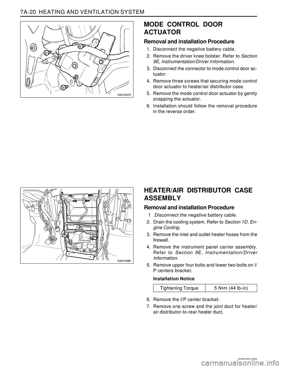
MODE CONTROL DOOR
ACTUATOR
Removal and installation Procedure
1. Disconnect the negative battery cable.
2. Remove the driver knee bolster. Refer to Section
9E, Instrumentation/Driver Information.
3. Disconnect the connector to mode control door ac-
tuator.
4. Remove three sxrews that securing mode control
door actuator to heater/air distributor case.
5. Remove the mode control door actuator by gently
snapping the actuator.
6. Installation should follow the removal procedure
in the reverse order.
Tightening Torque 5 Nm (44 lb-in)
KAA7A070
KAA7A080
HEATER/AIR DISTRIBUTOR CASE
ASSEMBLY
Removal and installation Procedure
1 .Disconnect the negative battery cable.
2. Drain the cooling system. Refer to Section 1D, En-
gine Cooling.
3. Remove the inlet and outlet heater hoses from the
firewall.
4. Remove the instrument panel carrier assembly.
Refer to Section 9E, Instrumentation/Driver
Information.
5. Remove upper four bolts and lower two bolts on I/
P centers bracket.
Installation Notice
6. Remove the I/P center bracket.
7. Remove one screw and the joint duct for heater/
air distributor-to-rear heater duct.
Page 1522 of 2053
HEATING AND VENTILATION SYSTEM 7A-21
SSANGYONG MY2002
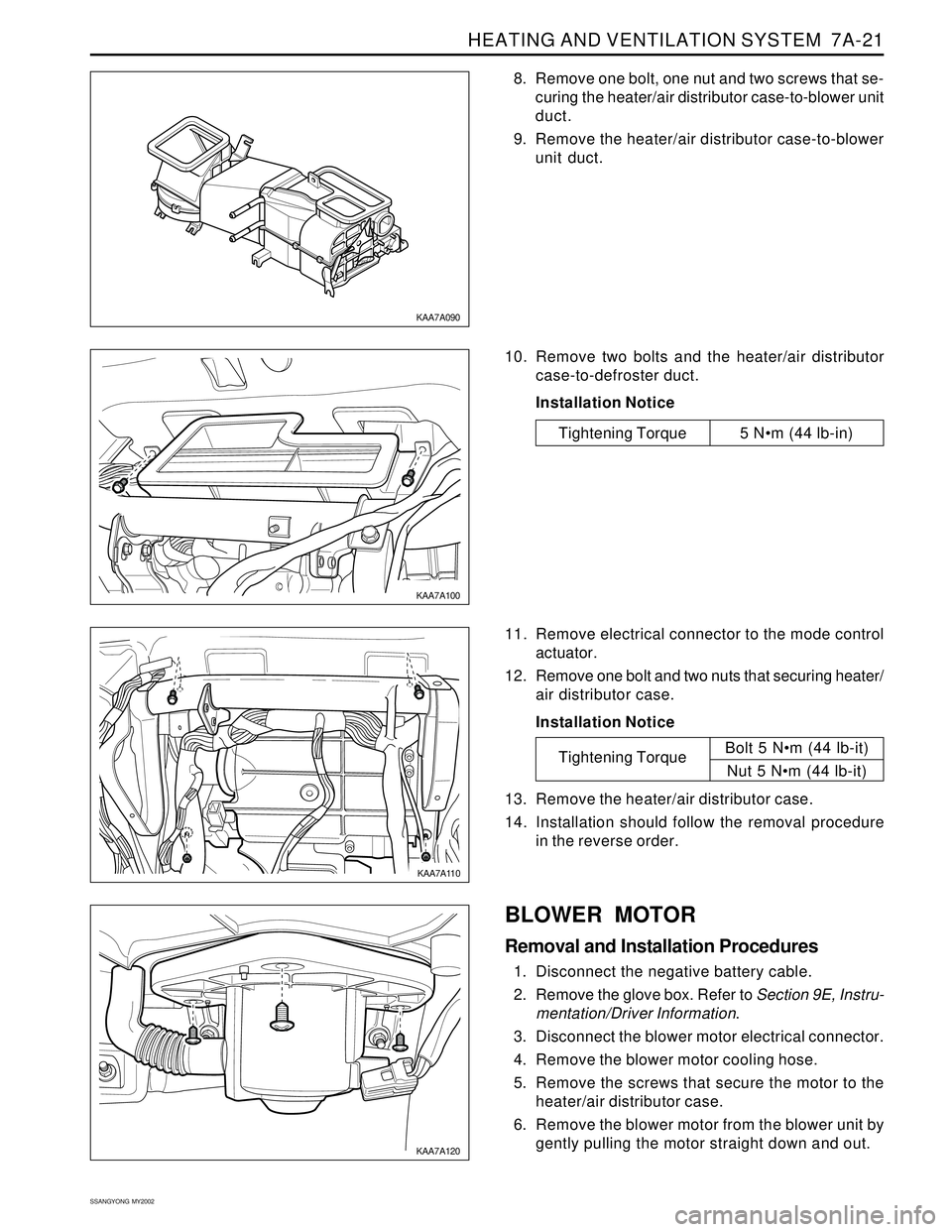
8. Remove one bolt, one nut and two screws that se-
curing the heater/air distributor case-to-blower unit
duct.
9. Remove the heater/air distributor case-to-blower
unit duct.
KAA7A090
KAA7A100
KAA7A110
KAA7A120
10. Remove two bolts and the heater/air distributor
case-to-defroster duct.
Installation Notice
11. Remove electrical connector to the mode control
actuator.
12. Remove one bolt and two nuts that securing heater/
air distributor case.
Installation Notice
13. Remove the heater/air distributor case.
14. Installation should follow the removal procedure
in the reverse order.
Tightening TorqueBolt 5 Nm (44 lb-it)
Nut 5 Nm (44 lb-it)
BLOWER MOTOR
Removal and Installation Procedures
1. Disconnect the negative battery cable.
2. Remove the glove box. Refer to Section 9E, Instru-
mentation/Driver Information.
3. Disconnect the blower motor electrical connector.
4. Remove the blower motor cooling hose.
5. Remove the screws that secure the motor to the
heater/air distributor case.
6. Remove the blower motor from the blower unit by
gently pulling the motor straight down and out.
Tightening Torque 5 Nm (44 lb-in)
Page 1523 of 2053
SSANGYONG MY2002
7A-22 HEATING AND VENTILATION SYSTEM
7. Installation should follow the removal procedure
in the reverse order.
Installation Notice: After install the blower motor
confirm that the blower motor operates properly.
KAA7A130
KAA7A140
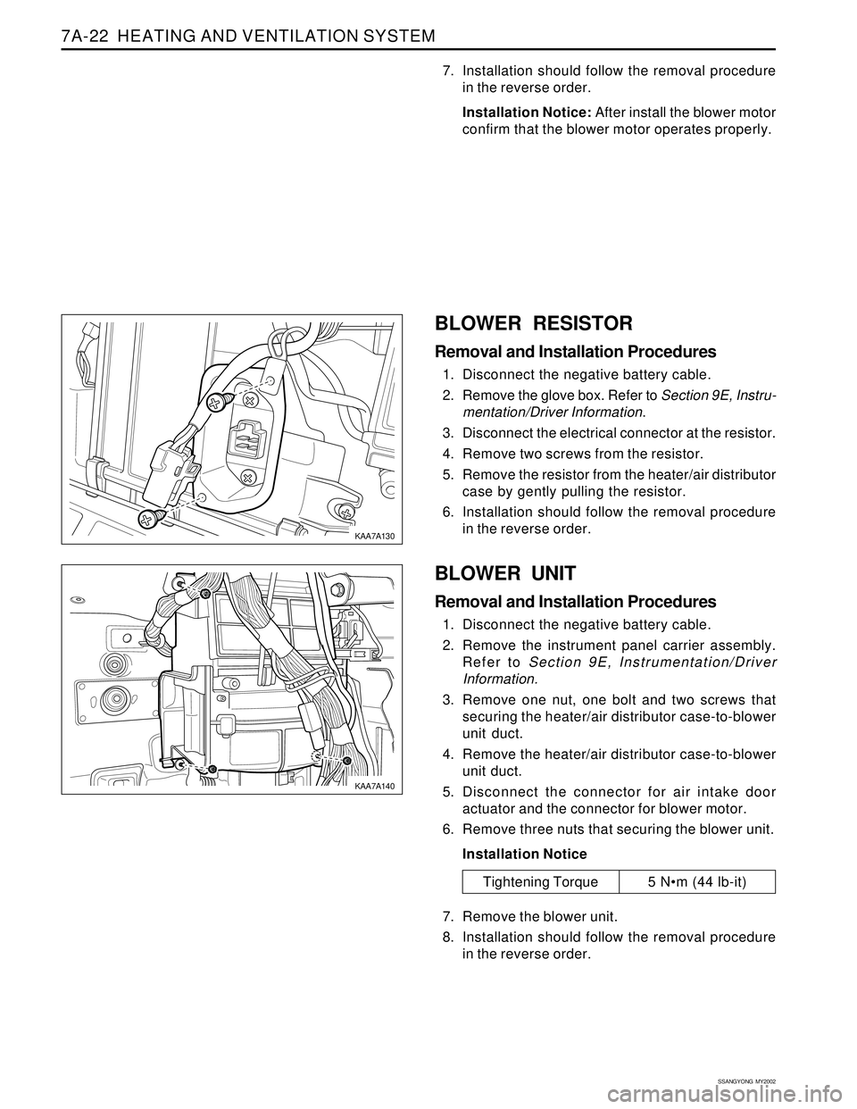
BLOWER RESISTOR
Removal and Installation Procedures
1. Disconnect the negative battery cable.
2. Remove the glove box. Refer to Section 9E, Instru-
mentation/Driver Information.
3. Disconnect the electrical connector at the resistor.
4. Remove two screws from the resistor.
5. Remove the resistor from the heater/air distributor
case by gently pulling the resistor.
6. Installation should follow the removal procedure
in the reverse order.
BLOWER UNIT
Removal and Installation Procedures
1. Disconnect the negative battery cable.
2. Remove the instrument panel carrier assembly.
Refer to Section 9E, Instrumentation/Driver
Information.
3. Remove one nut, one bolt and two screws that
securing the heater/air distributor case-to-blower
unit duct.
4. Remove the heater/air distributor case-to-blower
unit duct.
5. Disconnect the connector for air intake door
actuator and the connector for blower motor.
6. Remove three nuts that securing the blower unit.
Installation Notice
7. Remove the blower unit.
8. Installation should follow the removal procedure
in the reverse order.
Tightening Torque 5 Nm (44 lb-it)
Page 1525 of 2053
SSANGYONG MY2002
7A-24 HEATING AND VENTILATION SYSTEM
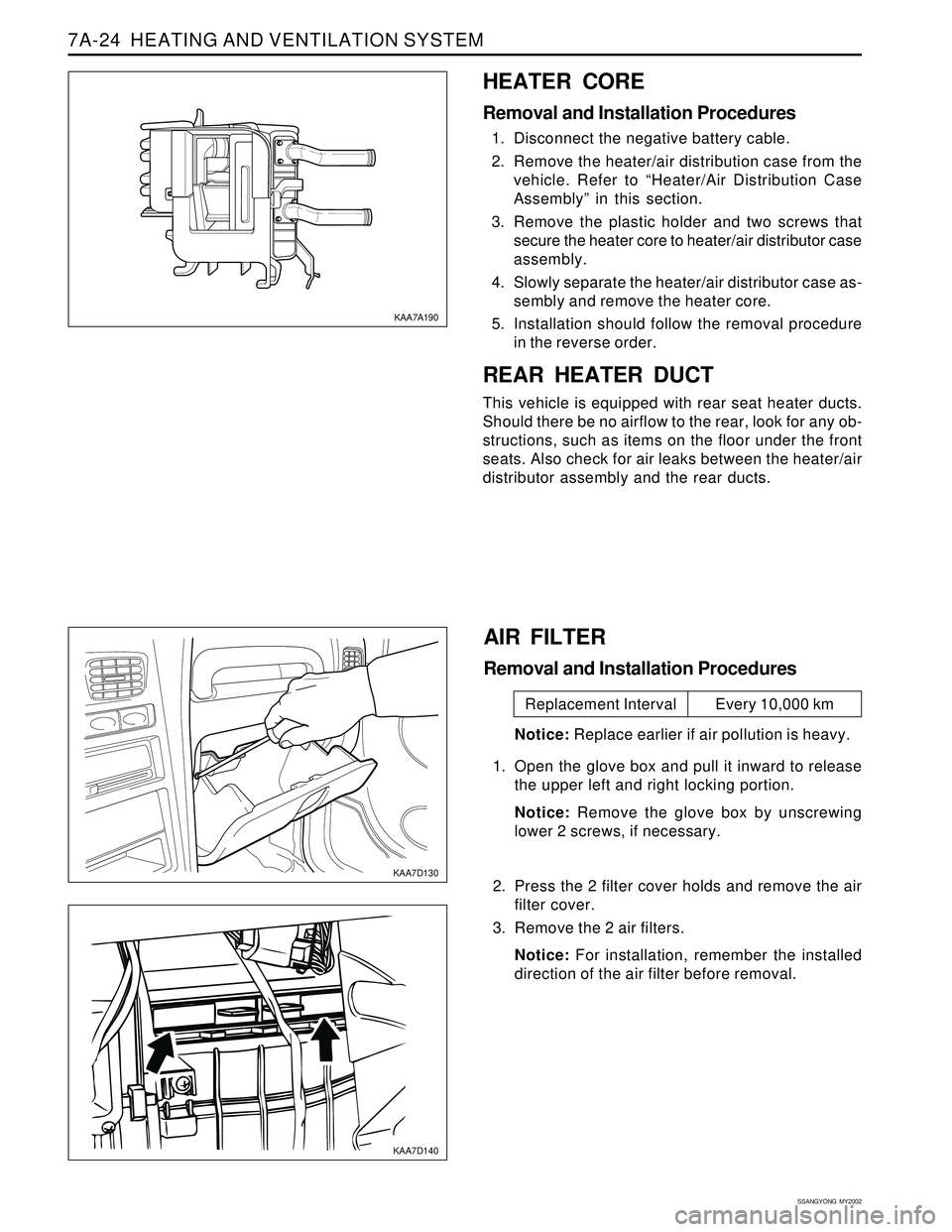
HEATER CORE
Removal and Installation Procedures
1. Disconnect the negative battery cable.
2. Remove the heater/air distribution case from the
vehicle. Refer to “Heater/Air Distribution Case
Assembly” in this section.
3. Remove the plastic holder and two screws that
secure the heater core to heater/air distributor case
assembly.
4. Slowly separate the heater/air distributor case as-
sembly and remove the heater core.
5. Installation should follow the removal procedure
in the reverse order.
REAR HEATER DUCT
This vehicle is equipped with rear seat heater ducts.
Should there be no airflow to the rear, look for any ob-
structions, such as items on the floor under the front
seats. Also check for air leaks between the heater/air
distributor assembly and the rear ducts.
KAA7A190
KAA7D130
KAA7D140
AIR FILTER
Removal and Installation Procedures
Notice: Replace earlier if air pollution is heavy.
1. Open the glove box and pull it inward to release
the upper left and right locking portion.
Notice: Remove the glove box by unscrewing
lower 2 screws, if necessary.
2. Press the 2 filter cover holds and remove the air
filter cover.
3. Remove the 2 air filters.
Notice: For installation, remember the installed
direction of the air filter before removal.
Replacement Interval Every 10,000 km
Page 1544 of 2053
MANUAL & SEMIAUTO-HVAC 7C-15
SSANGYONG MY2002
Important: Refer to the manufacturer’s
instructions for the charging station in use. It is
necessary to evacuate the system before
recharging it with new or recycled refrigerant.
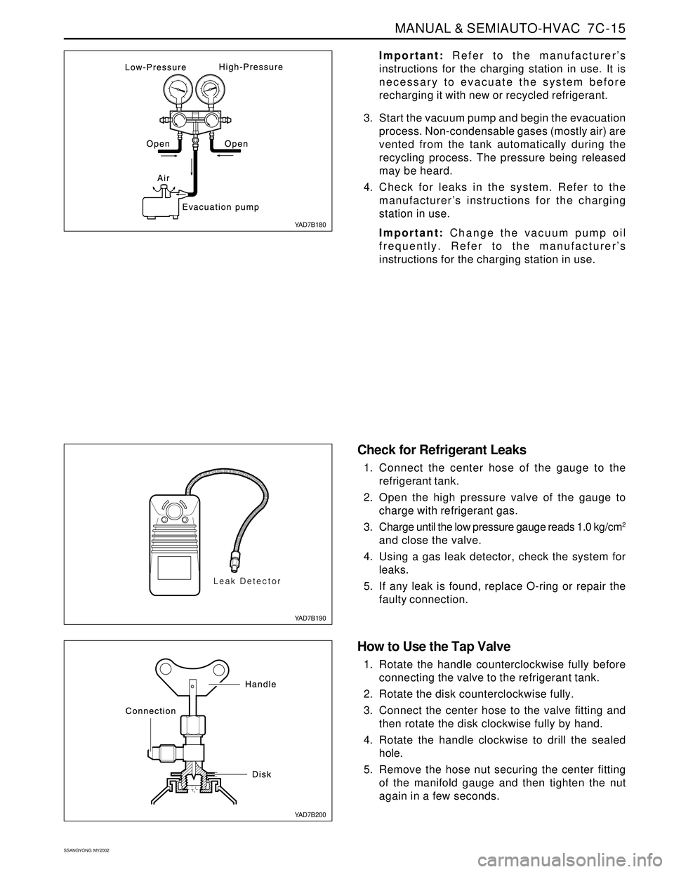
3. Start the vacuum pump and begin the evacuation
process. Non-condensable gases (mostly air) are
vented from the tank automatically during the
recycling process. The pressure being released
may be heard.
4. Check for leaks in the system. Refer to the
manufacturer’s instructions for the charging
station in use.
Important: Change the vacuum pump oil
frequently. Refer to the manufacturer’s
instructions for the charging station in use.
Check for Refrigerant Leaks
1. Connect the center hose of the gauge to the
refrigerant tank.
2. Open the high pressure valve of the gauge to
charge with refrigerant gas.
3. Charge until the low pressure gauge reads 1.0 kg/cm
2
and close the valve.
4. Using a gas leak detector, check the system for
leaks.
5. If any leak is found, replace O-ring or repair the
faulty connection.
How to Use the Tap Valve
1. Rotate the handle counterclockwise fully before
connecting the valve to the refrigerant tank.
2. Rotate the disk counterclockwise fully.
3. Connect the center hose to the valve fitting and
then rotate the disk clockwise fully by hand.
4. Rotate the handle clockwise to drill the sealed
hole.
5. Remove the hose nut securing the center fitting
of the manifold gauge and then tighten the nut
again in a few seconds.
YAD7B180
YAD7B190
YAD7B200
Page 1560 of 2053

SSANGYONG MY2002
7D-6 FATC-HAVC
FATC BLOCK DIAGRAM
INCAR SENSOR
AMBIENT SENSOR
WATER TEMPERATURE SENSOR
SUN LOAD SENSOR
TEMPERATURE SWITCH
BLOWER SWITCH
MODE SWITCH
DEFROSTER SWITCH
INTAKE SWITCH
AUTO SWITCH
A/CON SWITCH
OFF SWITCH
TEMP DOOR POSITION FEEDBACK
VOLTAGE
POWER TRANSISTOR COLLECTOR
VOLTAGE
VFD
MAX HI RELAY
POWER T/R
BLOWER
MOTOR
ECUCOMPRESSOR
MIX ACTUATORMIX DOOR
INTAKE ACTUATORINTAKE DOOR
MODE ACTUATORMODE DOOR
Airconditioner output
C
O
N
T
R
O
L
U
N
I
T
Page 1578 of 2053
SSANGYONG MY2002
8A-2 SEAT BELTS
DESCRIPTION AND OPERATION
DRIVER SEAT BELT WARNING
The driver’s seat belt incorporates a seat belt warning
lamp in the instrument cluster to remind the driver if
the seat belt is not fastened when the ignition is turned
ON. The warning lamp blinks for eight seconds with
chime and goes out.
THREE-POINT FRONT SEAT BELT
WITH PRETENSIONER
The front seat belt contains an electronically controlled
pyrotechnic retractor, pretensioner, which reduces seat
belt slack when it activated in a head-on or angled
front collision. The front seat belt must be replaced
after an accident that causes its activation. At normal
condition the driver’s seat belt operates as emergency
locking retractor (ELR).
Emergency Locking Retractor (ELR)
The ELR seat belt is always unlocked, allowing the
passenger freedom of movement, except in
emergencies such as rapid deceleration, rapid
acceleration, or hard cornering maneuvers.
THREE-POINT REAR OUTBOARD
SEAT BELT
The rear outboard seating position uses the emergency
locking retractor (ELR). Refer to Three-point front seat
belt with pretensioner in this section for details.
TWO-POINT LAP REAR CENTER
SEAT BELT
The two-point lap rear center seat belt is a single contin-
uous length of webbing. The webbing is routed from
the anchor through plate and into a single retractor.
OPERATIONAL AND FUNCTIONAL
CHECKS
Caution:
Keep sharp objects and potentially damaged ob
jects away from seat belts.
Avoid bending or damaging any portion of
buckle or the latch plate
Do not breach or dye the belt webbing. Use only
mild soap and water in order to clean the belts.
When installing the seat belt anchor bolts and
screws, start the bolts and screws by hand in or-
der to prevent cross-threading.
Do not attempt any repairs on the retractor mech-
anisms or covers. Replace any defective assem-
blies with new assemblies.
Replace any belts that are cut or damaged in any
way.
1. Inspect all seat anchor bolts and screws in order to
verify that they are secure.
2. Inspect the seat belt buckle. The buckle must lock
and unlock easily.
3. After inserting the latch into the buckle, tug sharply
on the belt. The buckle must remain locked.
4. Fully extend the shoulder belt portion to make sure
that there is no twisting or tears in the belt.
5. Let the shoulder belt retract fully. The belt should
retract easily.
CHILD SEAT TETHER ANCHOR
There are three child seat tether anchors to hold the
child seat firmly. One is located rear center of ceiling
and two are located on the rear corner of floor.
Page 1599 of 2053
SSANGYONG MY2002
8B-14 SUPPLEMENTAL RESTRAINTS SYSTEM
Yes
Go to Step 3
System OK
Go to “SDM
Integrity
Check”
Go to Step 6No
Go to Step 2
-
Go to Step 4
Go to Step 4 Value
-
-
9 v
9 - 16 vStep
1
2
3
4Action
Check the SDM connector to verify that it is properly
connected to the SDM.
Is the SDM connector properly connected?
Connect the SDM connector.
Is the repair complete?
1. Turn the ignition OFF.
2. Disconnect the SDM connector.
3. Turn the ignition ON.
4. Check the voltage at SDM connector terminal 5.
Is the ignition voltage greater than the specified value?
1. Turn the ignition ON.
2. Check the voltage supply to the airbag fuse F31.
Is the voltage within the specified value?
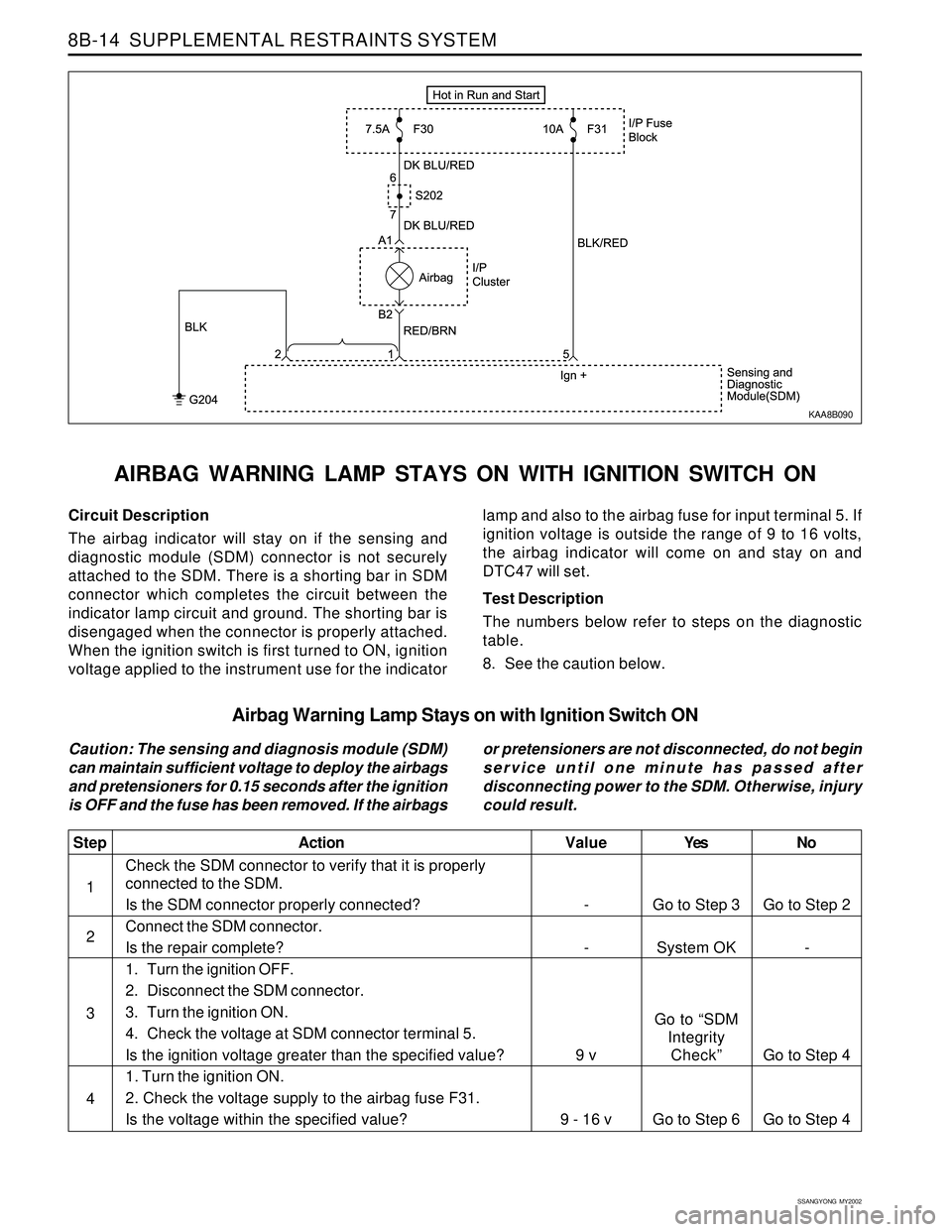
Circuit Description
The airbag indicator will stay on if the sensing and
diagnostic module (SDM) connector is not securely
attached to the SDM. There is a shorting bar in SDM
connector which completes the circuit between the
indicator lamp circuit and ground. The shorting bar is
disengaged when the connector is properly attached.
When the ignition switch is first turned to ON, ignition
voltage applied to the instrument use for the indicator
AIRBAG WARNING LAMP STAYS ON WITH IGNITION SWITCH ON
lamp and also to the airbag fuse for input terminal 5. If
ignition voltage is outside the range of 9 to 16 volts,
the airbag indicator will come on and stay on and
DTC47 will set.
Test Description
The numbers below refer to steps on the diagnostic
table.
8. See the caution below.
KAA8B090
Airbag Warning Lamp Stays on with Ignition Switch ON
Caution: The sensing and diagnosis module (SDM)
can maintain sufficient voltage to deploy the airbags
and pretensioners for 0.15 seconds after the ignition
is OFF and the fuse has been removed. If the airbagsor pretensioners are not disconnected, do not begin
service until one minute has passed after
disconnecting power to the SDM. Otherwise, injury
could result.