Page 1291 of 2053
5A-196 AUTOMATIC TRANSMISSION
SSANGYONG MY2002
21. Install solenoid 5. Ensure that the solenoid is
pushed firmly into the valve body by the retainer
and that the screw is tightened to specification.
Installation Notice
22. Install the detent spring assembly (spring, support
plate and screw), ensuring that the screw is tight-
ened to specification. Check the spring for wear
or damage.
Installation Notice
23. Install the manual shift valve.
Notice: Be aware that the manual valve will fall out
of the valve body.
24. Align the valve body assembly on the
transmission case and install the manual valve
lever to manual valve link. Fit the long end of the
link to the manual valve first. Install the securing
bolts and tighten to specification in the specified
sequence.
Installation Notice
KAA5A1Y0 KAA5A1X0
KAA5A1Z0 KAA5A1W0
Tightening Torque8 - 12 Nm
(71 - 106 lb-in)
Tightening Torque20 - 22 Nm
(15 - 16 lb-ft)
Tightening Torque8 - 13 Nm
(71 - 115 lb-in)
Page 1292 of 2053
AUTOMATIC TRANSMISSION 5A-197
SSANGYONG MY2002
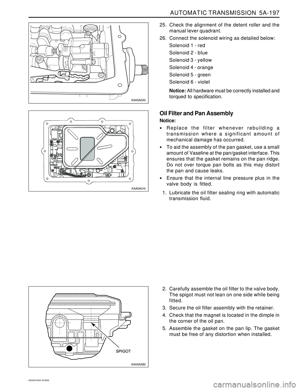
2. Carefully assemble the oil filter to the valve body.
The spigot must not lean on one side while being
fitted.
3. Secure the oil filter assembly with the retainer.
4. Check that the magnet is located in the dimple in
the corner of the oil pan.
5. Assemble the gasket on the pan lip. The gasket
must be free of any distortion when installed. 25. Check the alignment of the detent roller and the
manual lever quadrant.
26. Connect the solenoid wiring as detailed below:
Solenoid 1 - red
Solenoid 2 - bIue
Solenoid 3 - yellow
Solenoid 4 - orange
Solenoid 5 - green
Solenoid 6 - violet
Notice: All hardware must be correctly installed and
torqued to specification.
Oil Filter and Pan Assembly
Notice:
Replace the filter whenever rebuilding a
transmission where a significant amount of
mechanical damage has occurred.
To aid the assembly of the pan gasket, use a small
amount of Vaseline at the pan/gasket interface. This
ensures that the gasket remains on the pan ridge.
Do not over torque pan bolts as this may distort
the pan and cause leaks.
Ensure that the internal line pressure plus in the
valve body is fitted.
1. Lubricate the oil filter sealing ring with automatic
transmission fluid.
KAA5A2B0 KAA5A2A0
KAA5A510
Page 1293 of 2053
5A-198 AUTOMATIC TRANSMISSION
SSANGYONG MY2002
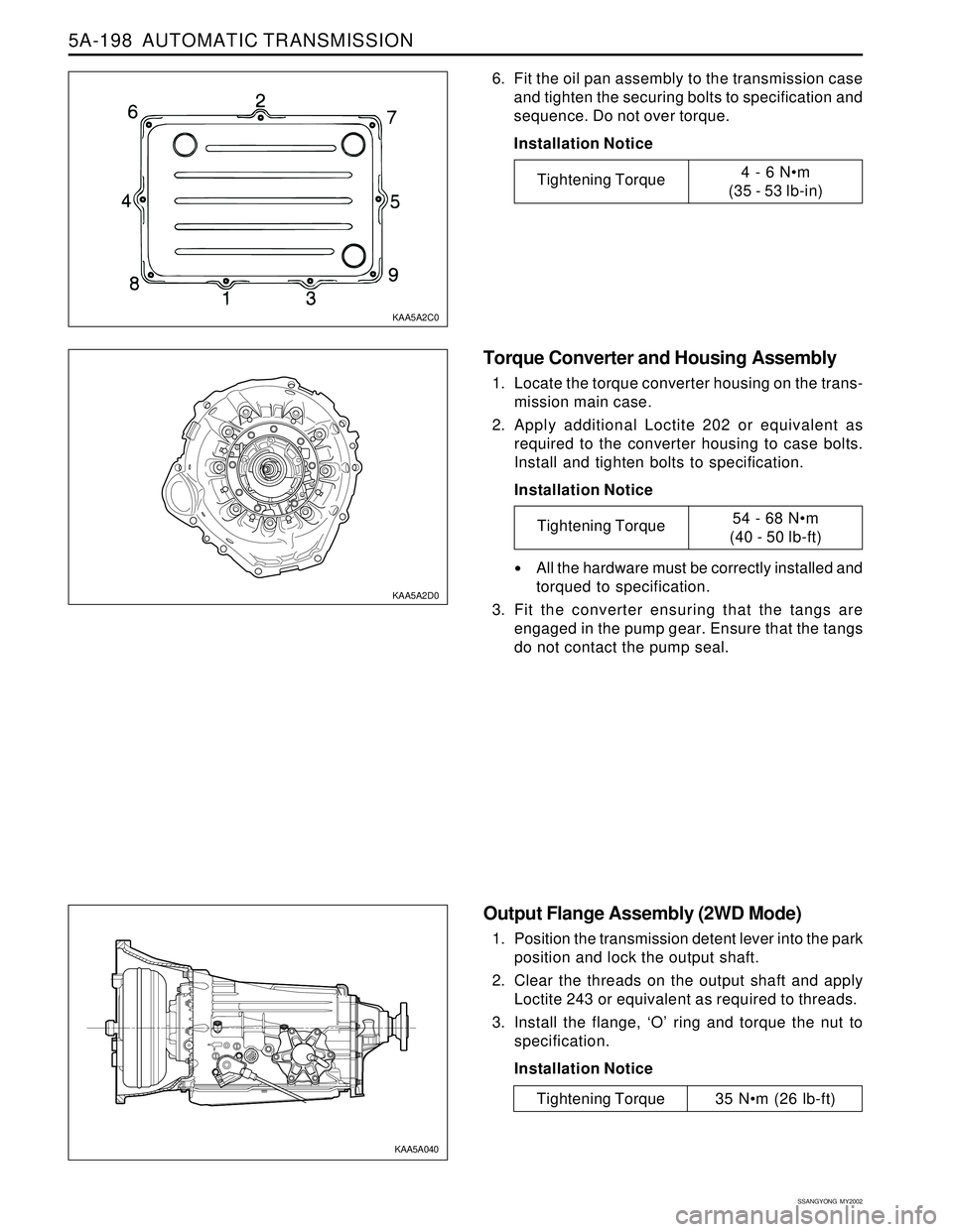
Torque Converter and Housing Assembly
1. Locate the torque converter housing on the trans-
mission main case.
2. Apply additional Loctite 202 or equivalent as
required to the converter housing to case bolts.
Install and tighten bolts to specification.
Installation Notice
All the hardware must be correctly installed and
torqued to specification.
3. Fit the converter ensuring that the tangs are
engaged in the pump gear. Ensure that the tangs
do not contact the pump seal.
Output Flange Assembly (2WD Mode)
1. Position the transmission detent lever into the park
position and lock the output shaft.
2. Clear the threads on the output shaft and apply
Loctite 243 or equivalent as required to threads.
3. Install the flange, ‘O’ ring and torque the nut to
specification.
Installation Notice
6. Fit the oil pan assembly to the transmission case
and tighten the securing bolts to specification and
sequence. Do not over torque.
Installation Notice
KAA5A2C0
KAA5A2D0
KAA5A040
Tightening Torque4 - 6 Nm
(35 - 53 lb-in)
Tightening Torque54 - 68 Nm
(40 - 50 lb-ft)
Tightening Torque 35 Nm (26 lb-ft)
Page 1397 of 2053
TRANSFER CASE 5D1-75
SSANGYONG MY2002
KAA5D510
KAA5D520
KAA5D460
3. Install the front output shaft oil seal using oil seal
installer, if removed.
4. Install the front output shaft/flange and install the
snap ring.
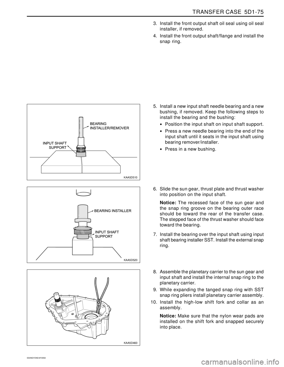
8. Assemble the planetary carrier to the sun gear and
input shaft and install the internal snap ring to the
planetary carrier.
9. While expanding the tanged snap ring with SST
snap ring pliers install planetary carrier assembly.
10. Install the high-low shift fork and collar as an
assembly.
Notice: Make sure that the nylon wear pads are
installed on the shift fork and snapped securely
into place. 6. Slide the sun gear, thrust plate and thrust washer
into position on the input shaft.
Notice: The recessed face of the sun gear and
the snap ring groove on the bearing outer race
should be toward the rear of the transfer case.
The stepped face of the thrust washer should face
toward the bearing.
7. Install the bearing over the input shaft using input
shaft bearing installer SST. Install the external snap
ring. 5. Install a new input shaft needle bearing and a new
bushing, if removed. Keep the following steps to
install the bearing and the bushing:
Position the input shaft on input shaft support.
Press a new needle bearing into the end of the
input shaft until it seats in the input shaft using
bearing remover/installer.
Press in a new bushing.
Page 1482 of 2053
SSANGYONG MY2002
6C-14 POWER STEERING GEAR
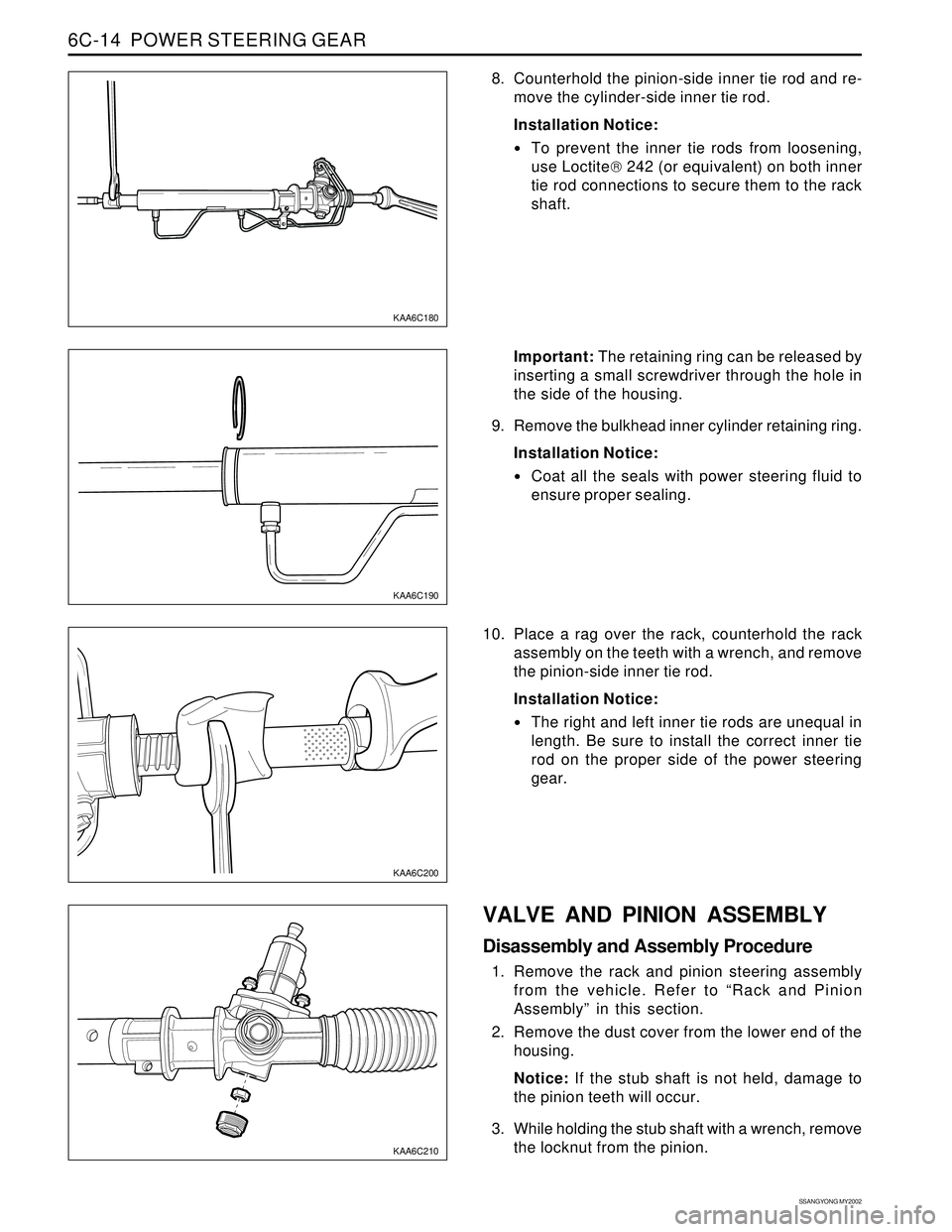
8. Counterhold the pinion-side inner tie rod and re-
move the cylinder-side inner tie rod.
Installation Notice:
To prevent the inner tie rods from loosening,
use Loctite 242 (or equivalent) on both inner
tie rod connections to secure them to the rack
shaft.
KAA6C180
KAA6C190
KAA6C210
KAA6C200
Important: The retaining ring can be released by
inserting a small screwdriver through the hole in
the side of the housing.
9. Remove the bulkhead inner cylinder retaining ring.
Installation Notice:
Coat all the seals with power steering fluid to
ensure proper sealing.
10. Place a rag over the rack, counterhold the rack
assembly on the teeth with a wrench, and remove
the pinion-side inner tie rod.
Installation Notice:
The right and left inner tie rods are unequal in
length. Be sure to install the correct inner tie
rod on the proper side of the power steering
gear.
VALVE AND PINION ASSEMBLY
Disassembly and Assembly Procedure
1. Remove the rack and pinion steering assembly
from the vehicle. Refer to “Rack and Pinion
Assembly” in this section.
2. Remove the dust cover from the lower end of the
housing.
Notice: If the stub shaft is not held, damage to
the pinion teeth will occur.
3. While holding the stub shaft with a wrench, remove
the locknut from the pinion.
Page 1488 of 2053
SSANGYONG MY2002
6E-2 POWER STEERING AND COLUMN
GENERAL DESCRIPTION
Caution: To ensure the energy-absorbing action of
the steering column, it is important to use only the
specified screws, bolts, and nuts, tightened to the
specified torque.
In addition to the steering function, the steering column
provides safety and security.
The energy-absorbing column is designed to compress
in a front-end collision to lessen the chance of driver
injury.
The ignition switch and the lock are mounted on the
column, allowing the ignition and steering operations
to be locked to inhibit theft of the car.
The column levers trigger the turn signals, the headlight
beams, and the windshield washer and wipers.
A tilt steering column uses a spherical joint to allow
the steering wheel to tilt up and down. This enables
the driver to adjust the steering wheel to a comfortable
position.
Notice: Apply a thin coat of lithium grease to all friction
points when reassembling.
The column may be disassembled and reassembled
easily.
DESCRIPTION AND OPERATION
IGNITION SWITCH KEYHOLE LAMP
For description and lamp replacement information, Re-
fer to Section 9B, Lighting Systems.
IGNITION KEY REMINDER
The ignition key reminder alerts the driver that the key
is still in the ignition when the driver attempts to exit
the vehicle.
An internal switch in the ignition lock cylinder supplies
battery voltage to the reminder chime module when all
of the following conditions are true:
•The key is in the ignition switch.
The ignition is OFF.
The driver’s door is open.
For information on removal and installation of the re-
minder chime module, Refer to Section 9E, Instrumen-
tation/Driver Information.
Page 1519 of 2053
SSANGYONG MY2002
7A-18 HEATING AND VENTILATION SYSTEM
ON-VEHICLE SERVICE
TEMPREATURE CONTROL CABLE
ADJUSTMENT
Because the cable and the cable housing have fixed
lengths, it is impossible to make a temperature cable
adjustment.
The heater/air distributor case linkage also cannot be
adjusted.
If a malfunction is suspected, verify the proper
operation of the controller and the mechanical doors
for heater/air distributor case assembly.
MAINTENANCE AND REPAIR
KAA7A020
KAA7A030
CONTROLLER ASSEMBLY AND
TEMPERATURE CONTROL CABLE
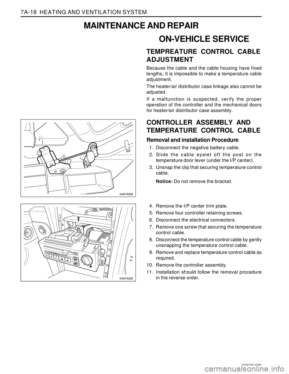
Removal and installation Procedure
1. Disconnect the negative battery cable.
2. Slide the cable eyelet off the post on the
temperature door lever (under the I/P center).
3. Unsnap the clip that securing temperature control
cable.
Notice: Do not remove the bracket.
4. Remove the I/P center trim plate.
5. Remove four controller retaining screws.
6. Disconnect the electrical connectors.
7. Remove one screw that securing the temperature
control cable.
8. Disconnect the temperature control cable by gently
unsnapping the temperature control cable.
9. Remove and replace temperature control cable as
required.
10. Remove the controller assembly.
11. Installation should follow the removal procedure
in the reverse order.
Page 1520 of 2053
HEATING AND VENTILATION SYSTEM 7A-19
SSANGYONG MY2002
CONTROL ASSEMBLY KNOB
LIGHTING
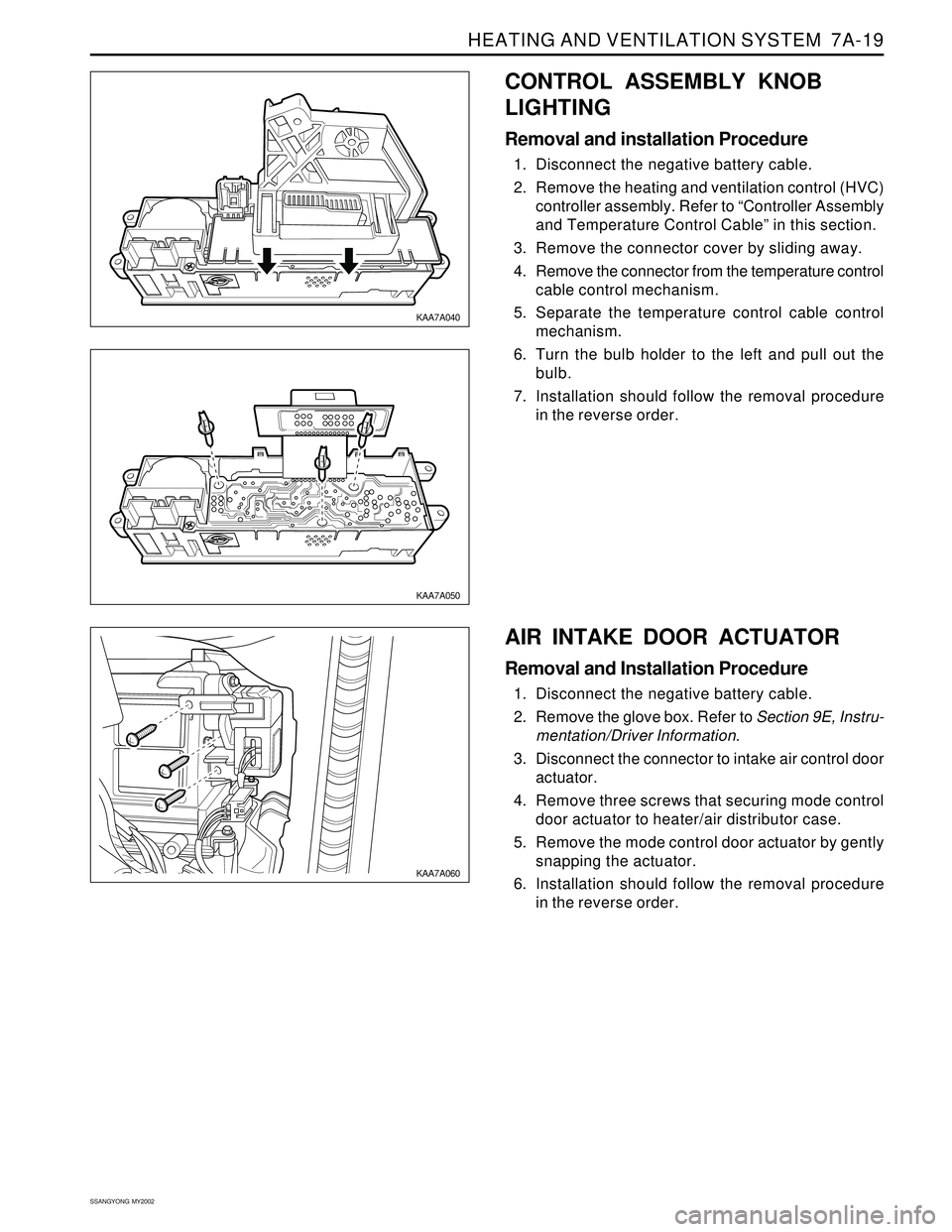
Removal and installation Procedure
1. Disconnect the negative battery cable.
2. Remove the heating and ventilation control (HVC)
controller assembly. Refer to “Controller Assembly
and Temperature Control Cable” in this section.
3. Remove the connector cover by sliding away.
4. Remove the connector from the temperature control
cable control mechanism.
5. Separate the temperature control cable control
mechanism.
6. Turn the bulb holder to the left and pull out the
bulb.
7. Installation should follow the removal procedure
in the reverse order.
KAA7A040
KAA7A050
KAA7A060
AIR INTAKE DOOR ACTUATOR
Removal and Installation Procedure
1. Disconnect the negative battery cable.
2. Remove the glove box. Refer to Section 9E, Instru-
mentation/Driver Information.
3. Disconnect the connector to intake air control door
actuator.
4. Remove three screws that securing mode control
door actuator to heater/air distributor case.
5. Remove the mode control door actuator by gently
snapping the actuator.
6. Installation should follow the removal procedure
in the reverse order.