Page 1256 of 2053
AUTOMATIC TRANSMISSION 5A-161
SSANGYONG MY2002
DISASSEMBLY PROCEDURE
Transmission
Tools Required
0555-336256Transmission Bench Cradle
0555-336257Pump Puller
Notice:
Remove the inhibitor switch before washing the
transmission in solvent or hot wash.
It is assumed that the transmission fluid has been
drained when the transmission was removed from
the vehicle and that the ‘special tools’ quoted are
available.
The transmission is dismantled in a modular fashion,
and the details of disassembly for each module are
given under the appropriate subject. Refer to Special
Tools Table in this chapter for details of all special
tools required when performing disassembly
procedures.
Technicians overhauling these transmissions will
also require a selection of good quality Torx bit
sockets, in particular numbers 30, 40 and 50, and
an 8 mm, 10 mm and 12 mm double hex socket.
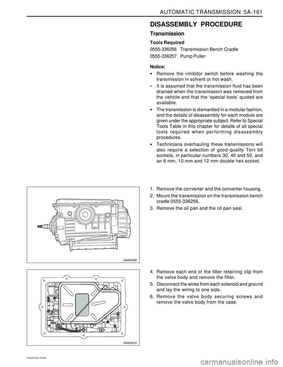
1. Remove the converter and the converter housing.
2. Mount the transmission on the transmission bench
cradle 0555-336256.
3. Remove the oil pan and the oil pan seal.
4. Remove each end of the filter retaining clip from
the valve body and remove the filter.
5. Disconnect the wires from each solenoid and ground
and lay the wiring to one side.
6. Remove the valve body securing screws and
remove the valve body from the case.
KAA5A500
KAA5A510
Page 1266 of 2053

AUTOMATIC TRANSMISSION 5A-171
SSANGYONG MY2002
ASSEMBLY PROCEDURE
Transmission
Tools Required
0555-336256Transmission Bench Cradle
0555-336258 C r o s s Shaft Pin Remover/Installer
(Detent Lever)
0555-336262Cross Shaft Seal Installer
0555-336263Cross Shaft bullet
0555-336265 C r o s s Shaft Pin Remover/Installer
(Inhibitor Switch)
Notice:
The transmission is assembled in modular fashion
and details of assembly for each module are given
under the appropriate subject.
Technicians overhauling these transmissions will
also require a selection of good quality Torx bit
sockets, in particular numbers 30, 40 and 50, and
an 8 mm, 10 mm and 12 mm double hex socket.
Ensure that the B1R circlip is fitted to the case. (If
this is not fitted, the valve will peen its way into
and through the separator plate)
Ensure that the ’E’clip is fitted to the cross shaft.
Ensure that all aspects of the parking mechanism
are working.
3. Assemble the B1R valve and spring, and secure
with the circlip. Ensure that the circlip is completely
seated in its groove. 1. Turn the transmission case upside down on the
bench and mount it to the transmission bench cradle
0555-336256.
2. Install all fittings, plugs and the breather, applying
a sealant where applicable, Tighten the fittings to
specifications. Ensurethatthebreatheris clear,
andcheckthat the lube fitting in the rear of the case
is fittedand clear of obstruction.
KAA5A500
KAA5A880
Page 1267 of 2053
5A-172 AUTOMATIC TRANSMISSION
SSANGYONG MY2002
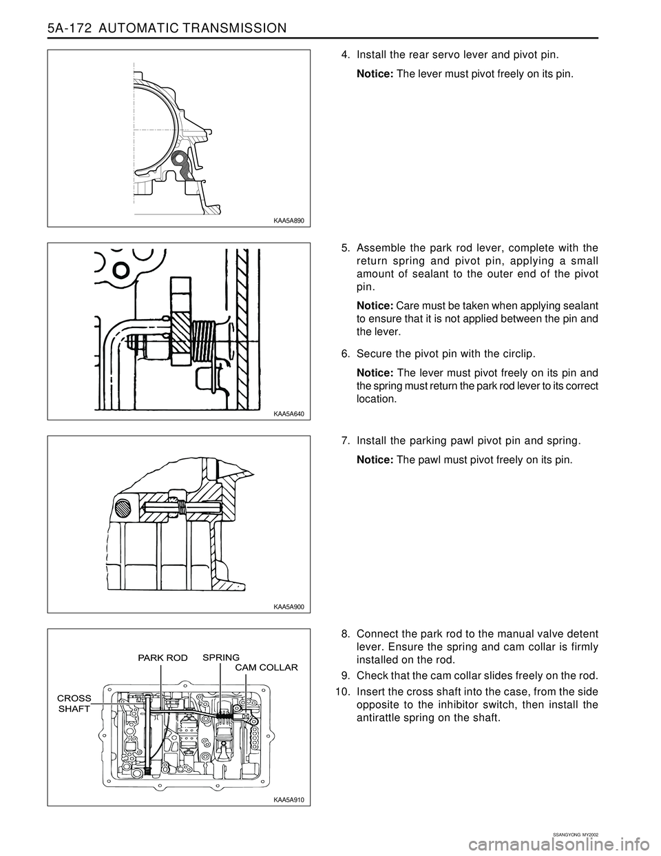
4. Install the rear servo lever and pivot pin.
Notice: The lever must pivot freely on its pin.
5. Assemble the park rod lever, complete with the
return spring and pivot pin, applying a small
amount of sealant to the outer end of the pivot
pin.
Notice: Care must be taken when applying sealant
to ensure that it is not applied between the pin and
the lever.
6. Secure the pivot pin with the circlip.
Notice: The lever must pivot freely on its pin and
the spring must return the park rod lever to its correct
location.
7. Install the parking pawl pivot pin and spring.
Notice: The pawl must pivot freely on its pin.
8. Connect the park rod to the manual valve detent
lever. Ensure the spring and cam collar is firmly
installed on the rod.
9. Check that the cam collar slides freely on the rod.
10. Insert the cross shaft into the case, from the side
opposite to the inhibitor switch, then install the
antirattle spring on the shaft.
KAA5A890
KAA5A640
KAA5A900
KAA5A910
Page 1269 of 2053
5A-174 AUTOMATIC TRANSMISSION
SSANGYONG MY2002
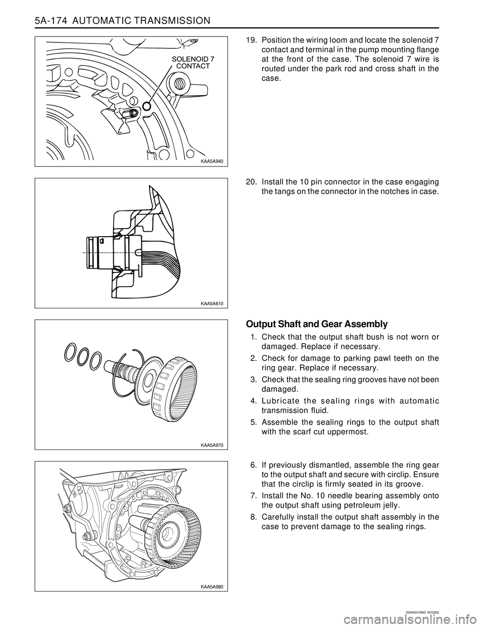
19. Position the wiring loom and locate the solenoid 7
contact and terminal in the pump mounting flange
at the front of the case. The solenoid 7 wire is
routed under the park rod and cross shaft in the
case.
20. Install the 10 pin connector in the case engaging
the tangs on the connector in the notches in case.
Output Shaft and Gear Assembly
1. Check that the output shaft bush is not worn or
damaged. Replace if necessary.
2. Check for damage to parking pawl teeth on the
ring gear. Replace if necessary.
3. Check that the sealing ring grooves have not been
damaged.
4. Lubricate the sealing rings with automatic
transmission fluid.
5. Assemble the sealing rings to the output shaft
with the scarf cut uppermost.
6. If previously dismantled, assemble the ring gear
to the output shaft and secure with circlip. Ensure
that the circlip is firmly seated in its groove.
7. Install the No. 10 needle bearing assembly onto
the output shaft using petroleum jelly.
8. Carefully install the output shaft assembly in the
case to prevent damage to the sealing rings.
KAA5A940
KAA5A610
KAA5A970
KAA5A980
Page 1277 of 2053
5A-182 AUTOMATIC TRANSMISSION
SSANGYONG MY2002
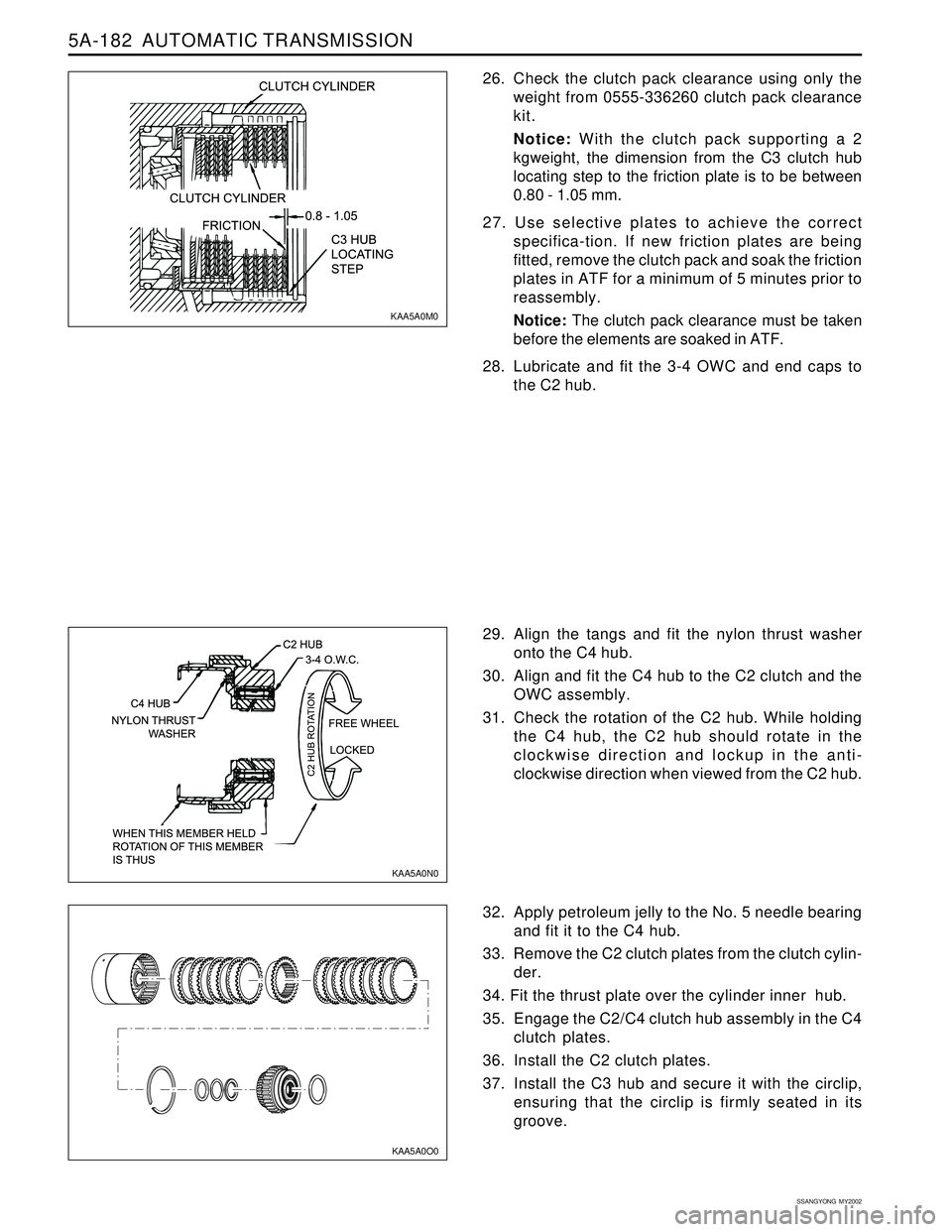
26. Check the clutch pack clearance using only the
weight from 0555-336260 clutch pack clearance
kit.
Notice: With the clutch pack supporting a 2
kgweight, the dimension from the C3 clutch hub
locating step to the friction plate is to be between
0.80 - 1.05 mm.
27. Use selective plates to achieve the correct
specifica-tion. If new friction plates are being
fitted, remove the clutch pack and soak the friction
plates in ATF for a minimum of 5 minutes prior to
reassembly.
Notice: The clutch pack clearance must be taken
before the elements are soaked in ATF.
28. Lubricate and fit the 3-4 OWC and end caps to
the C2 hub.
32. Apply petroleum jelly to the No. 5 needle bearing
and fit it to the C4 hub.
33. Remove the C2 clutch plates from the clutch cylin-
der.
34. Fit the thrust plate over the cylinder inner hub.
35. Engage the C2/C4 clutch hub assembly in the C4
clutch plates.
36. Install the C2 clutch plates.
37. Install the C3 hub and secure it with the circlip,
ensuring that the circlip is firmly seated in its
groove. 29. Align the tangs and fit the nylon thrust washer
onto the C4 hub.
30. Align and fit the C4 hub to the C2 clutch and the
OWC assembly.
31. Check the rotation of the C2 hub. While holding
the C4 hub, the C2 hub should rotate in the
clockwise direction and lockup in the anti-
clockwise direction when viewed from the C2 hub.
KAA5A0M0
KAA5A0N0
KAA5A0O0
Page 1282 of 2053
AUTOMATIC TRANSMISSION 5A-187
SSANGYONG MY2002
7. Check the fit of the C1 clutch hub on the overdrive
shaft. If it is loose, the hub and shaft assembly
must be replaced.
8. Coat the small nylon thrust spacer with petroleum
jelly and install it over the overdrive shaft.
9. Carefully fit the overdrive shaft into the C1 cylinder
so as not to damage the sealing ring.
10. Fit the small bronze C1 hub thrust washer in place
with petroleum jelly.
11. Check the input shaft for any defect. Fit the input
shaft into the cylinder and secure it with the circlip,
ensuring that the circlip is completely seated in
the groove.
KAA5A660
12. Coat the sealing rings with petroleum jelly and fit
onto the input shaft.
KAA5A1A0
13. Assemble the C1/C2/C4 clutch assembly to the
C3 clutch and sun gear assembly.
14. Install this assembly in the transmission case.
KAA5A1B0
Page 1287 of 2053
5A-192 AUTOMATIC TRANSMISSION
SSANGYONG MY2002
Valve Body
Notice:
Do not wash the nose of solenoids in solvent.
Be aware of ball positions in the upper valve body.
Be aware of 1 - 2 and 3 - 4 shift valve positions,
they can be swapped.
Check the 4 - 3 sequence valve and spring
orientation.
Check that the 12 mm ball is in the lower body.
Check the line pressure relief valve for swarf, and
be aware of replacing the shims.
When servicing the transmission, ensure that the
solenoid 5 damper spring is not broken.
Locate the detent spring central to the detent lever.
Wash the upper and lower valve bodies thoroughly
with cleansing solvent and blow dry.
Check the valve body cavities, ports and holes for
damage or obstructions.
The orifices in the valve body are for stability and
safeguard. Do not drill them larger.
Thoroughly wash all loose components.
Check that all valves slide freely in their location.
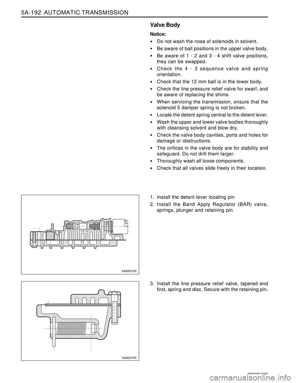
1. Install the detent lever locating pin
2. Install the Band Apply Regulator (BAR) valve,
springs, plunger and retaining pin.
3. Install the line pressure relief valve, tapered end
first, spring and disc. Secure with the retaining pin.
KAA5A1O0
KAA5A1P0
Page 1290 of 2053
AUTOMATIC TRANSMISSION 5A-195
SSANGYONG MY2002
19. Holding the separator plate to the upper valve
body to prevent the check balls from falling out,
install the upper valve body on the lower valve
body. Install all screws finger tight then tighten
the screws to specification in the prescribed
sequence.
Installation Notice
The wiring loom ground wire eyelet terminal is
secured beneath the solenoid 1 retainer. 16. Install the reverse lockout valve, spring, plug and
retaining plate. Ensure that the valve is correctly
oriented.
17. Position the five nylon ball checks in the upper
valve body.
18. Fit the upper valve body gasket. Install the
separator plate over the upper valve body.
KAA5A830 KAA5A840 KAA5A1V0
Tightening Torque11 - 16 Nm
(8 - 12 lb-ft)
20. Install solenoids 1, 2, 3, 4 and 6. Ensure the
solenoid is firmly secured by the retainer and that
the screw is tightened to specification.
Installation Notice
8 - 12 Nm
(71 - 106 lb-in)