Page 1648 of 2053

SSANGYONG MY2002
8B-66 SUPPLEMENTAL RESTRAINTS SYSTEM
KAA8B080
DEPLOYED AIRBAG MODULE
DISPOSAL PROCEDURE
Caution: After deployment, a powdery residue may
be on the surface of the airbag. The powder consists
primarily of cornstarch (used to lubricate the bag
as it inflates) and by-products of the chemical
reaction. Sodium hydroxide dust (similar to lye
soap) is produced as a by-product of the deployment
reaction. The sodium hydroxide then quickly reacts
with atmospheric moisture and is converted to
sodium carbonate and sodium bicarbonate (also
known as baking soda). Therefore, it is unlikely that
sodium hydroxide will be present after deployment.
Caution: Wear gloves and eye protection during the
disposal procedure.
Caution: After deployment, the metal surfaces of the
airbag module will be hot. In order to avoid the risk
of an injury or a fire, do not place the deployed airbag
module near any flammable objects, and allow the
airbag module to cool for 30 minutes before handling.
Deploy an airbag or pretensioner before disposing of
it. This includes those in a whole vehicle being
scrapped. If the vehicle is still within the warranty
period contact the Daewoo regional service manager
for approval or special instructions before deploying
an airbag module or a pretensioner. Deployed airbag
module or pretensioner should be disposed of in the
same manner as other scrap parts, with the addition
of the following steps:
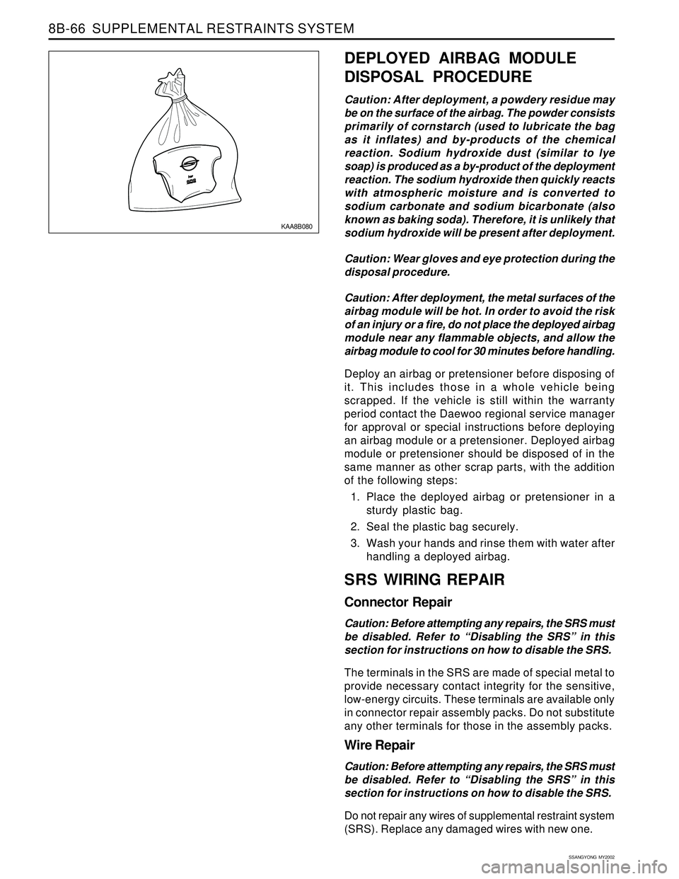
1. Place the deployed airbag or pretensioner in a
sturdy plastic bag.
2. Seal the plastic bag securely.
3. Wash your hands and rinse them with water after
handling a deployed airbag.
SRS WIRING REPAIR
Connector Repair
Caution: Before attempting any repairs, the SRS must
be disabled. Refer to “Disabling the SRS” in this
section for instructions on how to disable the SRS.
The terminals in the SRS are made of special metal to
provide necessary contact integrity for the sensitive,
low-energy circuits. These terminals are available only
in connector repair assembly packs. Do not substitute
any other terminals for those in the assembly packs.
Wire Repair
Caution: Before attempting any repairs, the SRS must
be disabled. Refer to “Disabling the SRS” in this
section for instructions on how to disable the SRS.
Do not repair any wires of supplemental restraint system
(SRS). Replace any damaged wires with new one.
Page 1691 of 2053
LIGHTING SYSTEM 9B-17
SSANGYONG MY2002
KAA9B070
REAR COMBINATION LAMPS
Removal and Installation Procedure
1. Disconnect the negative battery cable.
2. Remove the screws and the lamp assembly
3. Remove any inoperative bulb.
4. Installation should follow the removal procedure
in the reverse order.
KAA9B100
FOG LAMPS
Removal and Installation Procedure
1. Disconnect the negative battery cable.
2. Remove the bolts that secure the fog lamp
assembly
Installation Notice
Dissimilar metals in direct contact with each
other may corrode rapidly. Make sure to use
the correct fasteners to prevent premature
corrosion.
3. Remove the fog assembly.
4. Disconnect the fog lamp assembly electrical
connector.
Tightening Torque5 - 9 Nm
(44 - 80 lb-in)
KAA9B110
5. Remove the fog lamp dust cover.
6. Remove the locking clip.
7. Remove the bulb fromthefog lamp assembly.
8. Disconnect the bulb electrical connector.
9. Installation should follow the removal procedure
in the reverse order.
Page 1712 of 2053
SSANGYONG MY2002
9D-4 WIPER, WASHER SYSTEMS
KAA9D030
KAA9D040
3. Remove the nut and the wiper arm.
•Dissimilar metals in direct contact with each
other may corrode rapidly. Make sure to use
the correct fasteners to prevent premature
corrosion.
4. Installation should follow the removal procedure
in the reverse order.
WINDSHIELD WIPER MOTOR
Removal and Installation Procedure
1. Remove the left cowl top cover. Refer to “WIND-
SHIELD WIPER ARM” in this section.
2. Remove the center cowl top cover with the screws.
3. Remove the nut and the washer that secure the
wiper arm linkage to the motor driveshaft.
4. Pry the wiper arm linkage off the motor driveshaft.
KAA9D020
ON-VEHICLE SERVICE
UNIT REPAIR
WINDSHIELD WIPER ARM
Removal and Installation Procedure
1. Remove the left cowl top cover cap.
2. Remove the screws with the left cowl top cover.
REPAIR INSTRUCTIONS
Page 1734 of 2053

INSTRUMENTATION, DRIVER INFORMATION 9E-17
SSANGYONG MY2002
KAA9E270
16. Remove the left heat distributor duct with bolt.
Dissimilar metals in direct contact with each
other may corrode rapidly. Make sure to use
the correct fasteners to prevent premature
corrosion.
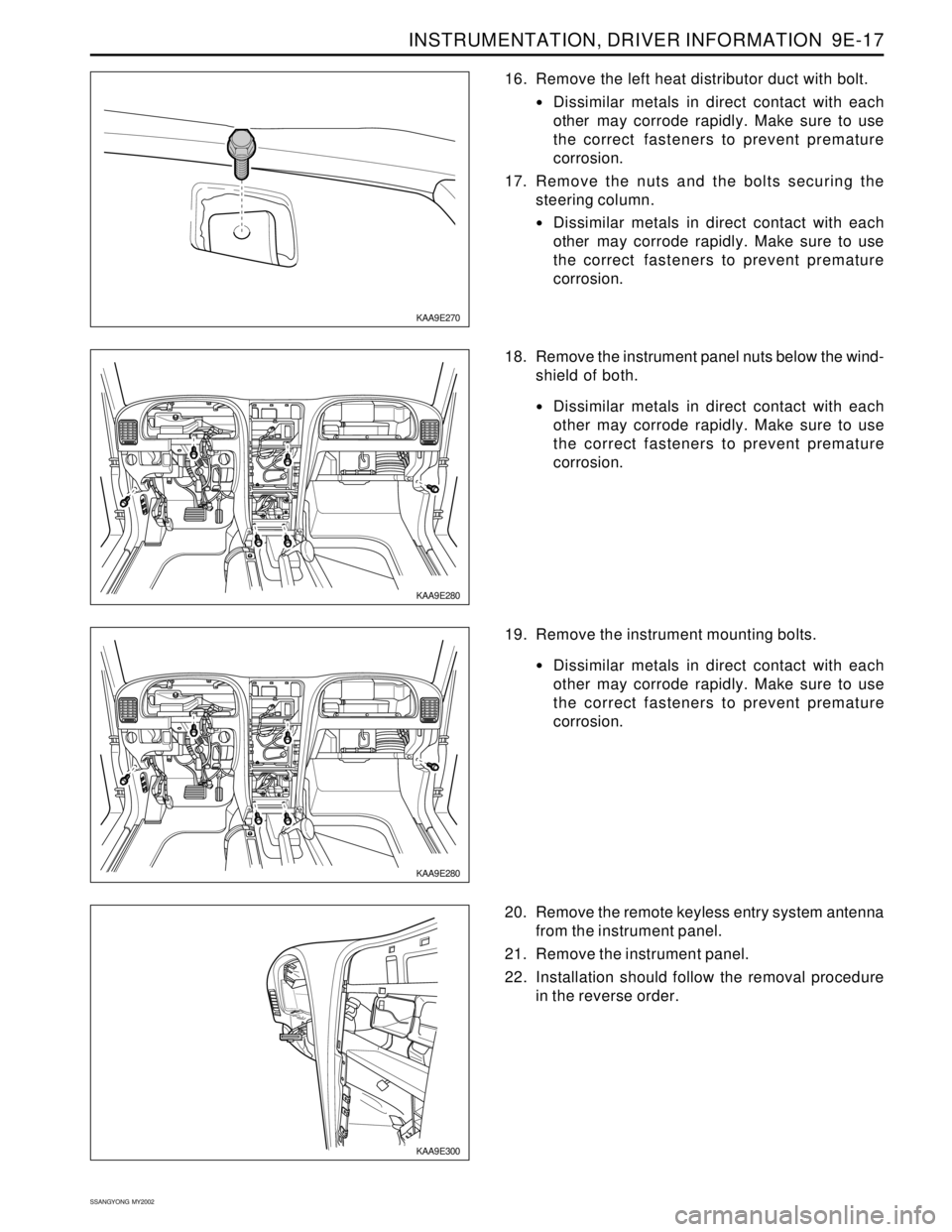
17. Remove the nuts and the bolts securing the
steering column.
Dissimilar metals in direct contact with each
other may corrode rapidly. Make sure to use
the correct fasteners to prevent premature
corrosion.
KAA9E280
18. Remove the instrument panel nuts below the wind-
shield of both.
Dissimilar metals in direct contact with each
other may corrode rapidly. Make sure to use
the correct fasteners to prevent premature
corrosion.
KAA9E300
20. Remove the remote keyless entry system antenna
from the instrument panel.
21. Remove the instrument panel.
22. Installation should follow the removal procedure
in the reverse order.
KAA9E280
19. Remove the instrument mounting bolts.
Dissimilar metals in direct contact with each
other may corrode rapidly. Make sure to use
the correct fasteners to prevent premature
corrosion.
Page 1780 of 2053

SSANGYONG MY2002
9K-2 SQUEAKS AND RATTLES
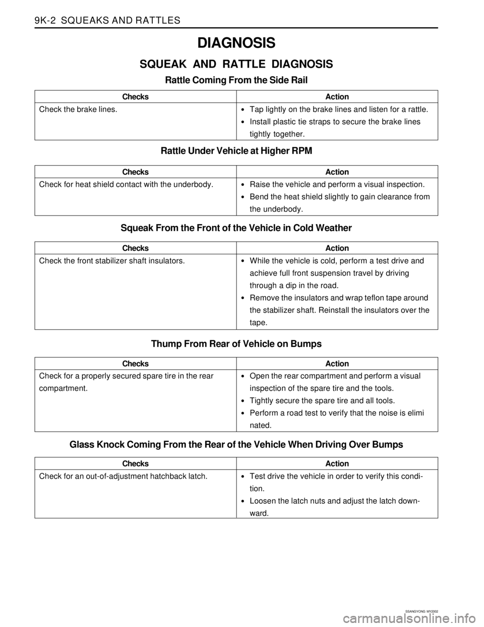
•Tap lightly on the brake lines and listen for a rattle.
Install plastic tie straps to secure the brake lines
tightly together.
Raise the vehicle and perform a visual inspection.
Bend the heat shield slightly to gain clearance from
the underbody.
While the vehicle is cold, perform a test drive and
achieve full front suspension travel by driving
through a dip in the road.
Remove the insulators and wrap teflon tape around
the stabilizer shaft. Reinstall the insulators over the
tape.
Open the rear compartment and perform a visual
inspection of the spare tire and the tools.
Tightly secure the spare tire and all tools.
Perform a road test to verify that the noise is elimi
nated.
DIAGNOSIS
SQUEAK AND RATTLE DIAGNOSIS
Rattle Coming From the Side Rail
Check the brake lines.ChecksAction
Rattle Under Vehicle at Higher RPM
Squeak From the Front of the Vehicle in Cold Weather
Check the front stabilizer shaft insulators.ChecksAction
Check for heat shield contact with the underbody.ChecksAction
Thump From Rear of Vehicle on Bumps
Check for a properly secured spare tire in the rear
compartment.ChecksAction
Glass Knock Coming From the Rear of the Vehicle When Driving Over Bumps
Check for an out-of-adjustment hatchback latch.ChecksActionTest drive the vehicle in order to verify this condi-
tion.
Loosen the latch nuts and adjust the latch down-
ward.
Page 1782 of 2053
SSANGYONG MY2002
9K-4 SQUEAKS AND RATTLES
MAINTENANCE AND REPAIR
ON-VEHICLE SERVICE
SQUEAK AND RATTLE REPAIR
Squeaks and rattles are caused by the unwanted move-
ment between parts of a vehicle. There are three means
to prevent squeaks or rattles.
Attach the parts securely so that there is no relative
motion during the operation of the vehicle.
Separate the parts so that there is no contact during
operation.
Insulate the parts so that no squeaks or rattles occur
with the movement of the parts. Low uniform friction
surfaces can be used to eliminate “stick-slip”
motion.
Page 1788 of 2053
SSANGYONG MY2002
9L-6 GLASS AND MIRRORS
KAA9L080
KAA9L090
KAA9L100
3. Remove the weatherstrip around the rear window.
7. Apply adhesive primer to the rear window frame
and the perimeter of the rear window.
KAA9L070
REAR WINDOW GLASS
Tools Required
J-24402Glass Sealant Remover
Removal and Installation Procedure
1. Disconnect the negative battery cable.
2. Disconnect the rear window defogger electrical
connector.
4. Remove the tailgate trim panel.
5. Remove the screws that secure the glass to the
tailgate panel.
6. Remove the glass from the tailgate panel.
Page 1791 of 2053

GLASS AND MIRRORS 9L-9
SSANGYONG MY2002
KAA9L160
KAA9L170
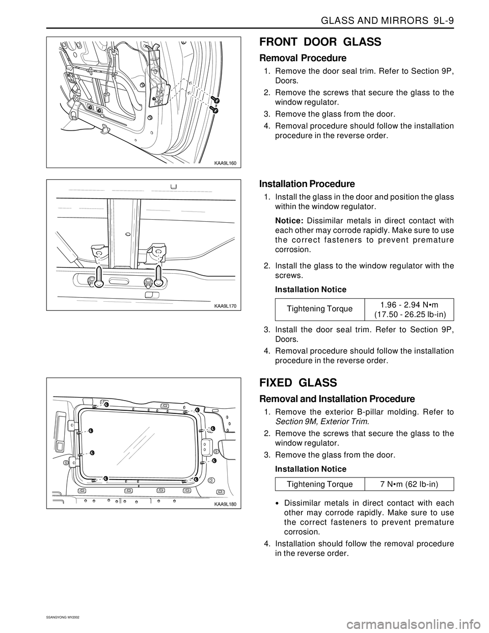
FRONT DOOR GLASS
Removal Procedure
1. Remove the door seal trim. Refer to Section 9P,
Doors.
2. Remove the screws that secure the glass to the
window regulator.
3. Remove the glass from the door.
4. Removal procedure should follow the installation
procedure in the reverse order.
Installation Procedure
1. Install the glass in the door and position the glass
within the window regulator.
Notice: Dissimilar metals in direct contact with
each other may corrode rapidly. Make sure to use
the correct fasteners to prevent premature
corrosion.
2. Install the glass to the window regulator with the
screws.
Installation Notice
3. Install the door seal trim. Refer to Section 9P,
Doors.
4. Removal procedure should follow the installation
procedure in the reverse order.
Tightening Torque1.96 - 2.94 Nm
(17.50 - 26.25 lb-in)
KAA9L180
FIXED GLASS
Removal and Installation Procedure
1. Remove the exterior B-pillar molding. Refer to
Section 9M, Exterior Trim.
2. Remove the screws that secure the glass to the
window regulator.
3. Remove the glass from the door.
Installation Notice
Dissimilar metals in direct contact with each
other may corrode rapidly. Make sure to use
the correct fasteners to prevent premature
corrosion.
4. Installation should follow the removal procedure
in the reverse order.
Tightening Torque 7 Nm (62 lb-in)