Page 385 of 2053
M161 ENGINE MECHANICAL 1B2 -- 97
D AEW OO M Y_2000
OIL PRESSURE RELIEF VALVE
Preceding Work: Removal of oil pan
1 Screw Plug 50 NSm (37 lb-ft) ................
2 Compression Spring3 Guide Pin
4Piston
Removal & Installation Procedure
1. Remove the screw plug (1).
Installation Notice
Tightening Torque
50 NSm (37 lb-ft)
2. Remove the spring (2), guide pin (3) and the piston
(4).
3. Installation should follow the removal procedure in
the reverse order.
Notice:Don’t use the seal for the screw plug.
Page 397 of 2053

1D2 -- 2 M161 ENGINE COOLING
D AEW OO M Y_2000
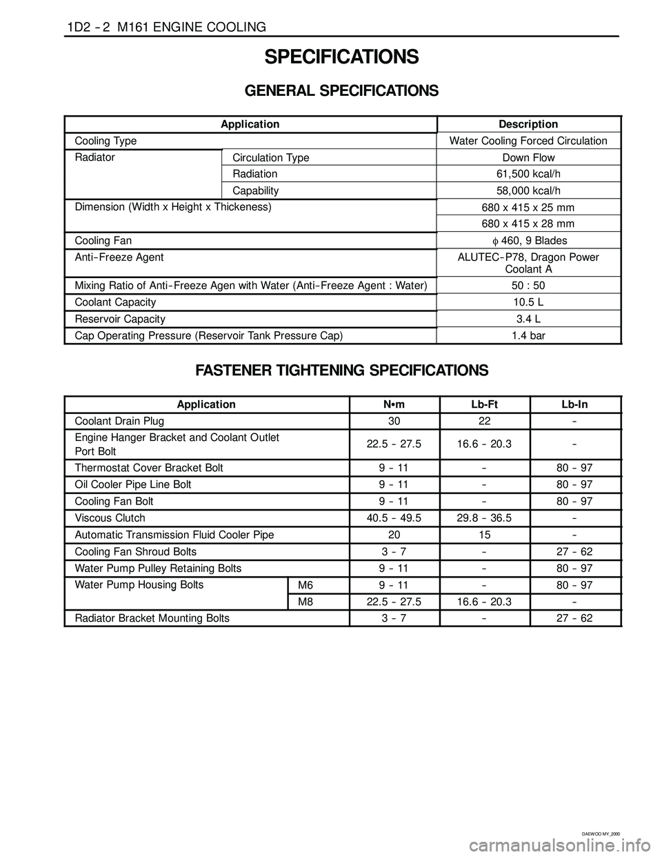
SPECIFICATIONS
GENERAL SPECIFICATIONS
ApplicationDescription
Cooling TypeWater Cooling Forced Circulation
RadiatorCirculation TypeDown Flow
Radiation61,500 kcal/h
Capability58,000 kcal/h
Dimension (Width x Height x Thickeness)680 x 415 x 25 mm(g)
680 x 415 x 28 mm
Cooling Fanφ460, 9 Blades
Anti-- Freeze AgentALUTEC-- P78, Dragon Power
Coolant A
Mixing Ratio of Anti-- Freeze Agen with Water (Anti-- Freeze Agent : Water)50 : 50
Coolant Capacity10.5 L
Reservoir Capacity3.4 L
Cap Operating Pressure (Reservoir Tank Pressure Cap)1.4 bar
FASTENER TIGHTENING SPECIFICATIONS
ApplicationNSmLb-FtLb-In
Coolant Drain Plug3022--
Engine Hanger Bracket and Coolant Outlet
Port Bolt22.5 -- 27.516.6 -- 20.3--
Thermostat Cover Bracket Bolt9--11--80 -- 97
Oil Cooler Pipe Line Bolt9--11--80 -- 97
Cooling Fan Bolt9--11--80 -- 97
Viscous Clutch40.5 -- 49.529.8 -- 36.5--
Automatic Transmission Fluid Cooler Pipe2015--
Cooling Fan Shroud Bolts3--7--27 -- 62
Water Pump Pulley Retaining Bolts9--11--80 -- 97
Water Pump Housing BoltsM69--11--80 -- 97pg
M822.5 -- 27.516.6 -- 20.3--
Radiator Bracket Mounting Bolts3--7--27 -- 62
Page 516 of 2053

1F2 -- 98 M161 ENGINE CONTROLS
D AEW OO M Y_2000
YAA1F180
14. Turn the roll over valves counterclockwise at an
angle of 90 degrees.
15. Turn the lock ring counterclockwise.
16. Remove and discard the gasket.
17. Installation should follow the removal procedure in
the reverse order.
YAA1F700
FUEL PRESSURE REGULATOR
Removal and Installation Procedure
1. Disconnect the negative battery cable.
2. Remove the fuel pressure test connector.
Installation Notice
Tightening Torque
25 NSm (18 Ib-ft)
YAA1F720
Caution: The fuel system is under pressure. To
avoid fuel spillage and the risk of personal injury or
fire, it is necessary to relieve the fuel system pres -
sure before disconnecting the fuel lines.
3. Relieve the fuel pressure in fuel supply system by
pressing the service valve.
YAA1F730
4. Disconnect the vacuum hose.
5. Disconnect the circlip and remove the fuel pressure
regulator.
6. Apply the oil to O-ring lightly and then replace it.
7. Perform a leak test of the fuel pressure regulator
with the engine off and the ignition on.
8. Installation should follow the removal procedure in
the reverse order.
Page 518 of 2053

1F2 -- 100 M161 ENGINE CONTROLS
D AEW OO M Y_2000
YAA1F770
Notice:Before removal, the fuel rail assembly may be
cleaned with a spray-type cleaner, following package in-
structions. Do not immerse the fuel rails in liquid clean-
ing solvent. Use care in removing the fuel rail assembly
to prevent damage to the electrical connectors and in-
jector spray tips. Prevent dirt and other contaminants
from entering open lines and passages. Fittings should
be capped and holes plugged during service.
Important:If an injector becomes separated from the
rail and remains in the cylinder head, replace the injector
O-ring seals and the retaining clip.
12. Remove the injectors and the fuel rail carefully.
13. Remove the fuel injector retainer clips.
14. Remove the fuel injectors by pulling them down and
out.
15. Discard the fuel injector O-rings.
16. Lubricate the new fuel injector O-rings with engine
oil. Install the new O-rings on the fuel injectors.
17. Perform a leak check of the fuel rail and fuel injec-
tors.
18. Installation should follow the removal procedure in
the reverse order.
YAA1F780
ENGINE COOLANT TEMPERATURE
SENSOR
Removal and Installation Procedure
1. Relieve the coolant system pressure.
2. Disconnect the negative battery cable.
3. Disconnect the engine coolant temperature sensor
connector.
Notice:Take care when handling the engine coolant
temperature sensor. Damage to the sensor will affect
the proper operation of the fuel injection system.
4. Remove the engine coolant temperature sensor
from the pump hosing.
Installation Notice
Tightening Torque
30 NSm (22 Ib-ft)
5. Installation should follow the removal procedure in
the reverse order.
Page 537 of 2053
1A3 -- 2 GENERAL ENGINE INFORMATION
D AEW OO M Y_2000
ENGINE SPECIFICATIONS (Cont’d)
ApplicationOM662LAOM661LA
Idle Speed (rpm)720 -- 820750 -- 850
Fuel Injection Pressure (bar)135 -- 143135 -- 143
Oil Capacity (liter)8.0 -- 9.56.5 -- 8.0
Lubrication TypeForced by Gear PumpForced by Gear Pump
Oil Filter TypeCombined Full-- Flow and Partial
Flow FilterCombined Full-- Flow and Partial
Flow Filter
FuelDieselDiesel
Page 545 of 2053

1A3 -- 10 GENERAL ENGINE INFORMATION
D AEW OO M Y_2000
DIAGNOSIS
OIL LEAK DIAGNOSIS
Most fluid oil leaks are easily located and repaired by
visually finding the leak and replacing or repairing the
necessary parts. On some occasions a fluid leak may be
difficult to locate or repair. The following procedures may
help you in locating and repairing most leaks.
Finding the Leak
1. Identify the fluid. Determine whether it is engine oil,
automatic transmission fluid, power steering fluid,
etc.
2. Identify where the fluid is leaking from.
2.1 After running the vehicle at normal operating
temperature, park the vehicle over a large sheet
of paper.
2.2 Wait a few minutes.
2.3 You should be able to find the approximate loca-
tion of the leak by the drippings on the paper.
3. Visually check around the suspected component.
Check around all the gasket mating surfaces for
leaks. A mirror is useful for finding leaks in areas that
are hard to reach.
4. If the leak still cannot be found, it may be necessary
to clean the suspected area with a degreaser, steam
or spray solvent.
4.1 Clean the area well.
4.2 Dry the area.
4.3 Operate the vehicle for several miles at normal
operating temperature and varying speeds.
4.4 After operating the vehicle, visually check the
suspected component.
4.5 If you still cannot locate the leak, try using the
powder or black light and dye method.
Powder Method
1. Clean the suspected area.
2. Apply an aerosol-- type powder (such as foot powder)
to the suspected area.
3. Operate the vehicle under normal operating condi-
tions.
4. Visually inspect the suspected component. You
should be able to trace the leak path over the white
powder surface to the source.
Black Light and Dye Method
A dye and light kit is available for finding leaks, Refer to
the manufacturer ’s directions when using the kit.
1. Pour the specified amount of dye into the engine oil fill
tube.
2. Operate the vehicle normal operating conditions as
directed in the kit.
3. Direct the light toward the suspected area. The dyed
fluid willappear as a yellow path leading to the
source.
Repairing the Leak
Once the origin of the leak has been pinpointed and
traced back to its source, the cause of the leak must be
determined n order for it to be repaired properly. If a gas-
ket is replaced, but the sealing flange is bent, the new
gasket will not repair the leak. Thebent flange must be
repaired also. Before attempting to repair a leak, check
for the following conditions and correct them as they
may cause a leak.
Gaskets
DThe fluid level/pressure is too high.
DThe crankcase ventilation system is malfunctioning.
DThe fasteners are tightened improperly or the threads
are dirty or damaged.
DThe flanges or the sealing surface is warped.
DThere are scratches, burrs or other damage to the
sealing surface.
DThe gasket is damaged or worn.
DThere is cracking or porosity of the component.
DAn improper seal was used (where applicable).
Seals
DThe fluid level/pressure is too high.
DThe crankcase ventilation system is malfunctioning.
DThe seal bore is damaged (scratched, burred or
nicked).
DThe seal is damaged or worn.
DImproper installation is evident.
DThere are cracks in the components.
DThe shaft surface is scratched, nicked or damaged.
DA loose or worn bearing is causing excess seal wear.
Page 549 of 2053

1A3 -- 14 GENERAL ENGINE INFORMATION
D AEW OO M Y_2000
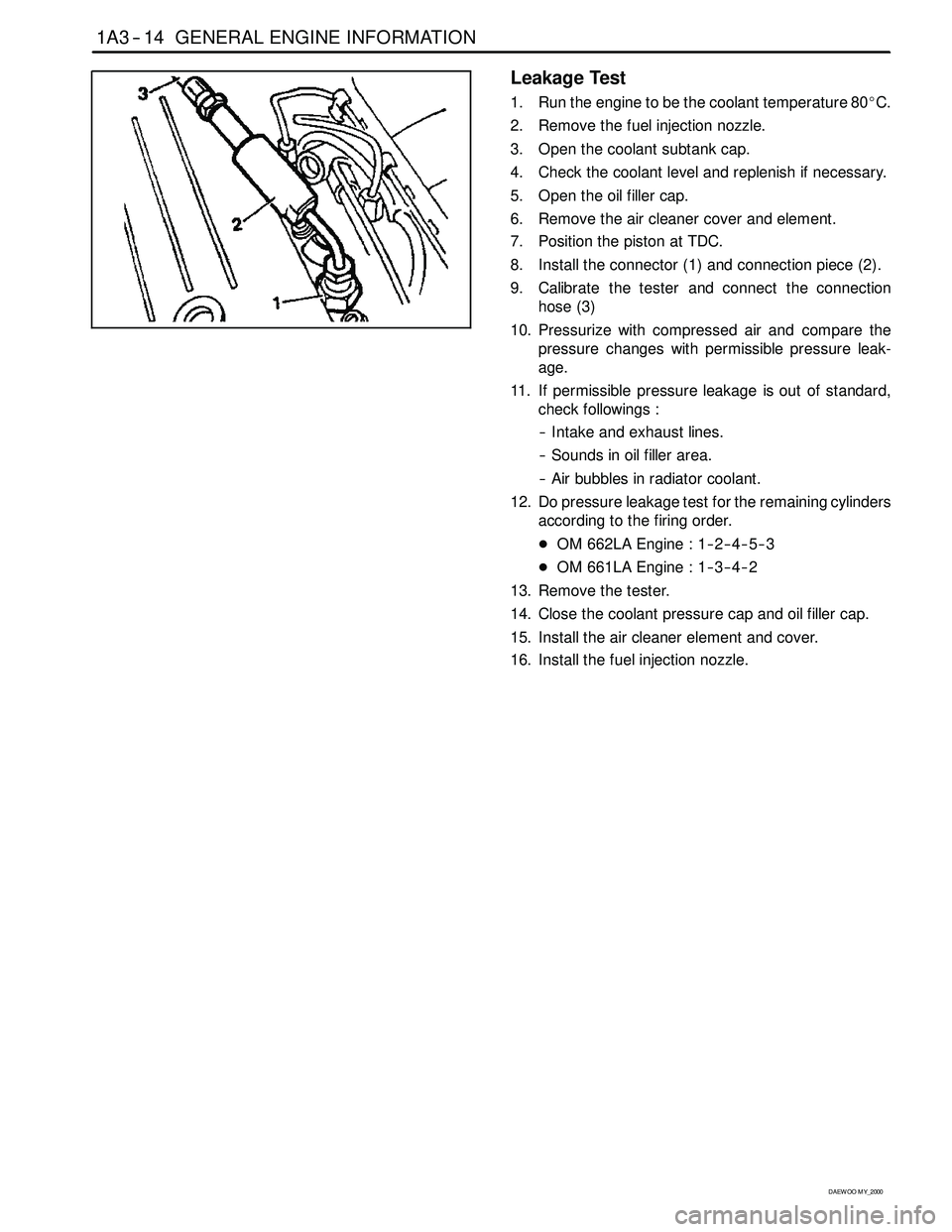
Leakage Test
1. Run the engine to be the coolant temperature 80_C.
2. Remove the fuel injection nozzle.
3. Open the coolant subtank cap.
4. Check the coolant level and replenish if necessary.
5. Open the oil filler cap.
6. Remove the air cleaner cover and element.
7. Position the piston at TDC.
8. Install the connector (1) and connection piece (2).
9. Calibrate the tester and connect the connection
hose (3)
10. Pressurize with compressed air and compare the
pressure changes with permissible pressure leak-
age.
11. If permissible pressure leakage is out of standard,
check followings :
-- Intake and exhaust lines.
-- Sounds in oil filler area.
-- Air bubbles in radiator coolant.
12. Do pressure leakage test for the remaining cylinders
according to the firing order.
DOM 662LA Engine : 1-- 2-- 4-- 5-- 3
DOM 661LA Engine : 1-- 3-- 4-- 2
13. Remove the tester.
14. Close the coolant pressure cap and oil filler cap.
15. Install the air cleaner element and cover.
16. Install the fuel injection nozzle.
Page 719 of 2053
1B3 -- 170 OM600 ENGINE MECHANICAL
D AEW OO M Y_2000
Remeval & Installation Procedure
1. Remove the oil filter cover and then drain the oil.
2. Remove the oil pressure switch line.
3. Remove the oil filter housing.
4. Clean the sealing surface.
5. Installation should follow the removal procedure in
the reverse order.