Page 257 of 2053

1F1 -- 94 M162 ENGINE CONTROLS
D AEW OO M Y_2000
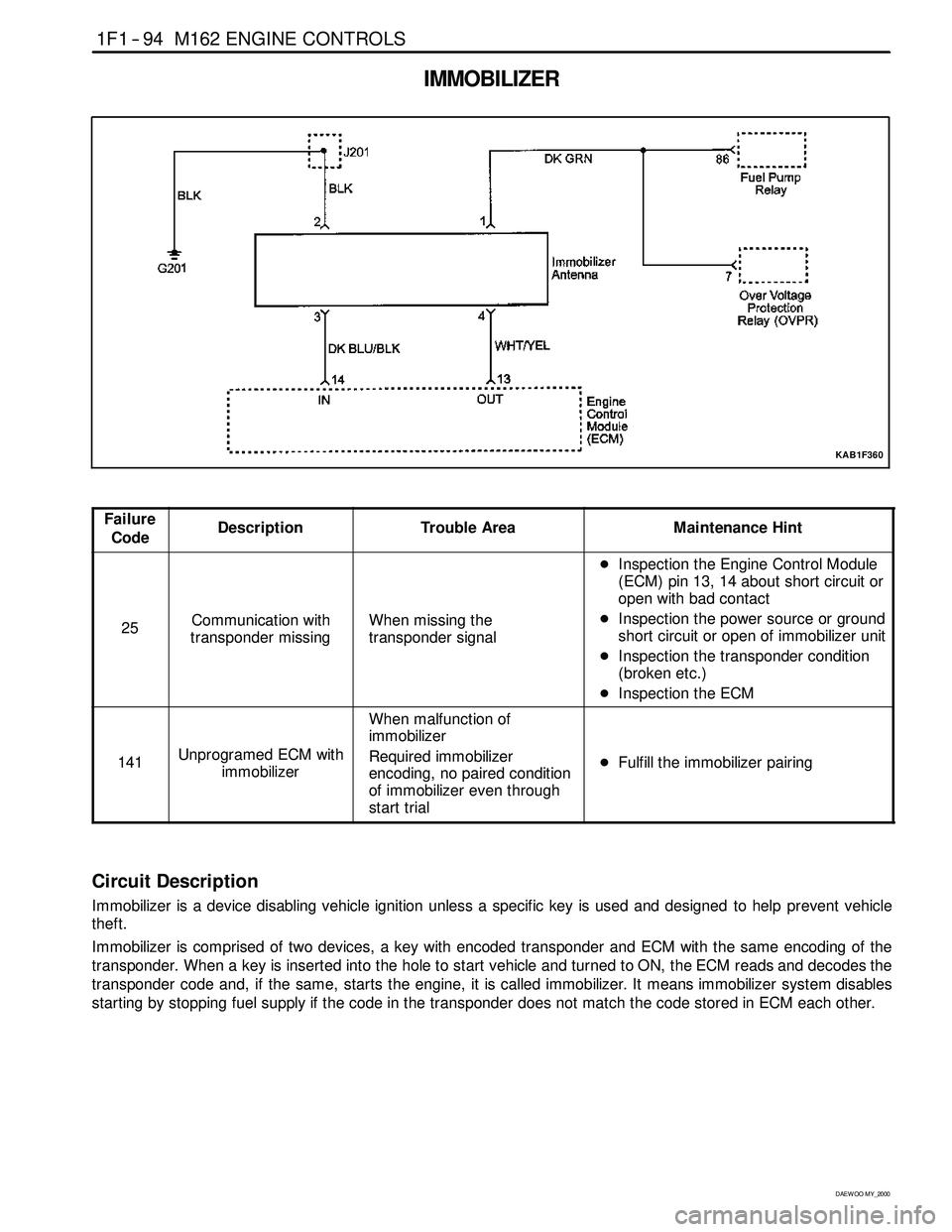
IMMOBILIZER
KAB1F360
Failure
CodeDescriptionTrouble AreaMaintenance Hint
25Communication with
transponder missingWhen missing the
transponder signal
DInspection the Engine Control Module
(ECM) pin 13, 14 about short circuit or
open with bad contact
DInspection the power source or ground
short circuit or open of immobilizer unit
DInspection the transponder condition
(broken etc.)
DInspection the ECM
141Unprogramed ECM with
immobilizer
When malfunction of
immobilizer
Required immobilizer
encoding, no paired condition
of immobilizer even through
start trial
DFulfill the immobilizer pairing
Circuit Description
Immobilizer is a device disabling vehicle ignition unless a specific key is used and designed to help prevent vehicle
theft.
Immobilizer is comprised of two devices, a key with encoded transponder and ECM with the same encoding of the
transponder. When a key is inserted into the hole to start vehicle and turned to ON, the ECM reads and decodes the
transponder code and, if the same, starts the engine, it is called immobilizer. It means immobilizersystem disables
starting by stopping fuel supply if the code in the transponder does not match the code stored in ECM each other.
Page 332 of 2053
M161 ENGINE MECHANICAL 1B2 -- 39
D AEW OO M Y_2000
BELT PULLEY AND VIBRATION DAMPER
Preceding Work: Removal of cooling fan and viscous clutch
Removal of fan shroud
Removal of drive belt
1 Vibration Damper Center
1st step 200+20 NSm (148+15 lb-ft) .........
2nd step 90°+10°rotation added2 Vibration Damper Disk
5 Vibration Damper Assembly
6Key
Page 333 of 2053
1B2 -- 40 M161 ENGINE MECHANICAL
D AEW OO M Y_2000
Components
1 Center Bolt (M18 x 50)
2 Center Bolt Washer
3 Vibration Damper and Pulley Assembly
4Key
5 Crankshaft Front Seal
6 Timing Gear Case Cover7 Crankshaft Sprocket (Camshaft Driven)
8 Crankshaft Sprocket (Oil pump Driven)
9 Crankshaft
10 Oil Pan
11 Oil Pan Gasket
12 Oil Pan Mounting Bolt (M6 x 22)
ServiceDataStandard
Permissble Deviation of The Vibration DamperRadial Runout0.6 mmp
Axial Runout0.6 mm
Page 335 of 2053
1B2 -- 42 M161 ENGINE MECHANICAL
D AEW OO M Y_2000
CRANKSHAFT FRONT RADIAL SEAL
Preceding Work: Removal of belt pulley and vibration damper
1 Center Bolt (M18 x 50)
1st step 200+20 NSm (148+15 lb-ft) .........
2nd step 90°+10°
2 Center Bolt Washer3 Crankshaft Front Seal Installer
4 Crankshaft Front Seal
5Key
Page 336 of 2053
M161 ENGINE MECHANICAL 1B2 -- 43
D AEW OO M Y_2000
Tools Required
601 589 03 14 00 Crankshaft Front Seal Installer
Replacement Procedure
1. Remove the radial seal with a screw driver.
Notice:Use a clean cloth not to damage the radial seal
mounting hole and the crankshaft.
2. Coat the radial sealing lip with engine oil.
3. Using the crankshaft front seal installer 601 589 03 14
00, assemble the radial seal .
4. Align the sleeve groove and the woodruff key and
tighten the center bolt until the center bolt and the
damper disk stop in the movement.
Installation Notice
Ti
ghteningTo rque
1st step: 200 + 20 NSm
(148 + 15 lb-ft)
TighteningTorque
2nd step: 90°+10°
5. Remove the crankshaft front seal installer 601 589 03
14 00, and install the belt pulley and the vibration
damper.
6. Check for leaks while operating the engine.
Page 374 of 2053
M161 ENGINE MECHANICAL 1B2 -- 81
D AEW OO M Y_2000
CRANKSHAFT SPROCKET
Preceding Work: Removal of oil pan
Removal of tensioning rail
Removal of crank case guide rail
1 Oil Pump Chain Tensioner
2 Oil Pump Chain Bushing
3 Oil Pump Chain Spring
4 Crankshaft Sprocket
5Key6 Bolt (M8 x 20, 1 piece) / Washer
29-- 35 NSm (21-- 26 lb-ft) ...................
7 Oil Pump Sprocket
8OilPump
9 Oil Pump Roller Chain
10 Timing Chain
Page 375 of 2053

1B2 -- 82 M161 ENGINE MECHANICAL
D AEW OO M Y_2000
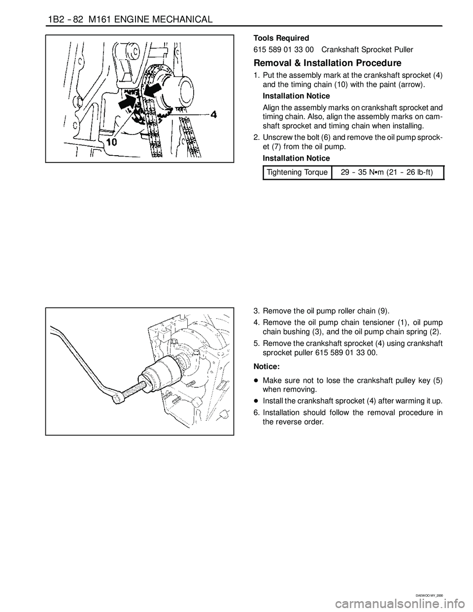
Tools Required
615 589 01 33 00 Crankshaft Sprocket Puller
Removal & Installation Procedure
1. Put the assembly mark at the crankshaft sprocket (4)
and the timing chain (10) with the paint (arrow).
Installation Notice
Align the assembly marks on crankshaft sprocket and
timing chain. Also, align the assembly marks on cam-
shaft sprocket and timing chain when installing.
2. Unscrew the bolt (6) and remove the oil pump sprock-
et (7) from the oil pump.
Installation Notice
Tightening Torque
29 -- 35 NSm (21 -- 26 lb-ft)
3. Remove the oil pump roller chain (9).
4. Remove the oil pump chain tensioner (1), oil pump
chain bushing (3), and the oil pump chain spring (2).
5. Remove the crankshaft sprocket (4) using crankshaft
sprocketpuller615589013300.
Notice:
DMake sure not to lose the crankshaft pulley key (5)
when removing.
DInstall the crankshaft sprocket (4) after warming it up.
6. Installation should follow the removal procedure in
the reverse order.
Page 436 of 2053

1F2 -- 14 M161 ENGINE CONTROLS
D AEW OO M Y_2000
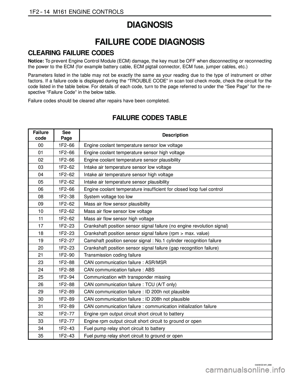
DIAGNOSIS
FAILURE CODE DIAGNOSIS
CLEARING FAILURE CODES
Notice:To prevent Engine Control Module (ECM) damage, the key must be OFF when disconnecting or reconnecting
the power to the ECM (for example battery cable, ECM pigtail connector, ECM fuse, jumper cables, etc.)
Parameters listed in the table may not be exactly the same as your reading due to the type of instrument or other
factors. If a failure code is displayed during the “TROUBLE CODE” in scan tool check mode, check the circuit for the
code listed in the table below. For details of each code, turn to the page referred to under the “See Page” for the re-
spective “Failure Code” in the below table.
Failure codes should be cleared after repairs have been completed.
FAILURE CODES TABLE
Failure
codeSee
PageDescription
001F2 -- 66Engine coolant temperature sensor low voltage
011F2 -- 66Engine coolant temperature sensor high voltage
021F2 -- 66Engine coolant temperature sensor plausibility
031F2 -- 62Intake air temperature sensor low voltage
041F2 -- 62Intake air temperature sensor high voltage
051F2 -- 62Intake air temperature sensor plausibility
061F2 -- 66Engine coolant temperature insufficient for closed loop fuel control
081F2 -- 38System voltage too low
091F2 -- 62Mass air flow sensor plausibility
101F2 -- 62Mass air flow sensor low voltage
111F2 -- 62Mass air flow sensor high voltage
171F2 -- 23Crankshaft position sensor signal failure (no engine revolution signal)
181F2 -- 23Crankshaft position sensor signal failure (rpm > max. value)
191F2 -- 27Camshaft position senosr signal : No.1 cylinder recognition failure
201F2 -- 23Crankshaft position sensor signal failure (gap recognition failure)
211F2 -- 90Transmission coding failure
231F2 -- 88CAN communication failure : ASR/MSR
241F2 -- 88CAN communication failure : ABS
251F2 -- 94Communication with transponder missing
261F2 -- 88CAN communication failure : TCU (A/T only)
291F2 -- 89CAN communication failure : ID 200h not plausible
301F2 -- 89CAN communication failure : ID 208h not plausible
311F2 -- 89CAN communication failure : communication initialization failure
321F2 -- 77Engine rpm output circuit short circuit to battery
331F2 -- 77Engine rpm output circuit short circuit to ground or open
341F2 -- 43Fuel pump relay short circuit to battery
351F2 -- 43Fuel pump relay short circuit to ground or open