Page 709 of 2053
1B3 -- 160 OM600 ENGINE MECHANICAL
D AEW OO M Y_2000
5. Place alignment marks (arrow) on the timing chain
(4) and crankshaft sprocket (12).
6. Remove the woodruff key(15).
7. Place alignment marks (arrow) on the timing chain
(4) and camshaft sprocket (3).
8. Remove the chain tensioner.
9. Remove the bolt (1) and then remove the washer (2)
and camshaft sprocket (3).
10. Remove the crankshaft sprocket (12) by using a
puller (20).
Puller 102 589 05 33 00
Page 710 of 2053
OM600 ENGINE MECHANICAL 1B3 -- 161
D AEW OO M Y_2000
Installation Procedure
1. Put the same alignment mark on the new crankshaft
sprocket as in the old sprocket.
Notice
Check the timing chain, camshaft sprocket, injection
pump timing sprocket, oil pump chain and oil pump
sprocket for wear and replace if necessary.
2. Install the new crankshaft sprocket (12) by using a
drift (21).
Notice
Align the groove of sprocket and woodruff key (ar-
row) exactly.
Drift 116 589 07 15 00
3. Fit the timing chain (4) on the crankshaft sprocket
(12).
Notice
Align the alignment marks (arrow) on the chain and
sprocket.
4. Install the camshaft sprocket (3).
Tightening Torque25 N∙m (18 lb-ft) + 90_
Notice
Pay attention on the alignment marks and dowel pin
(arrow).
Page 711 of 2053
1B3 -- 162 OM600 ENGINE MECHANICAL
D AEW OO M Y_2000
Notice
If the max. length ’L’ of the stretch bolt exceeds
53.6mm, replace it.
5. Fit the oil pump chain (9) on the crankshaft sprocket
(12) and insert the oil pump sprocket (8) into the oil
pump chain and then install it on the oil pump.
Notice
The curved side of the oil pump sprocket should
face the oil pump.
6. Insert the woodruff key (15).
7. Install the guide rail (16). Attach the spring (17) to
guide rail and to tensioning lever together onto the
bearing pins (5,6).
Notice
Ensure that the spring is correctly located in the
guide rail (arrow).
Page 808 of 2053
OM600 ENGINE CONTROLS 1F3 -- 5
D AEW OO M Y_2000
VACUUM CONTROLSYSTEM TEST
1 Ventilation (To Passenger Compartment)
2 Engine Cut -- Off Valve (Ignition Key Switch)
3 Auto-- locking Hub Solenoid Valve
4 Engine Stop Valve Unit
5 PLA Vacuum Unit (Idle Speed Adjustment)6Engine
7 Vacuum Pump
830_Thermovalve
9 Fuel Injection Pump
Test Data
Idle Speed IncreaseAt least 100 rpm at approx. 500mbr
Permissible Pressure Drop of System400 -- 500mbar approx. 1 min.
Page 1143 of 2053

5A-48 AUTOMATIC TRANSMISSION
SSANGYONG MY2002
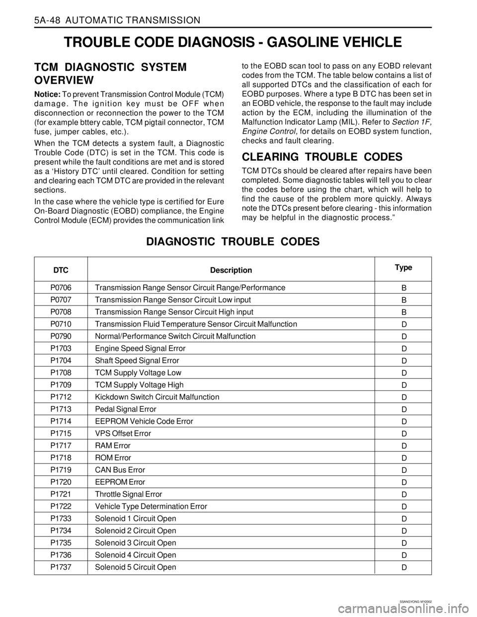
TROUBLE CODE DIAGNOSIS - GASOLINE VEHICLE
TCM DIAGNOSTIC SYSTEM
OVERVIEW
Notice: To prevent Transmission Control Module (TCM)
damage. The ignition key must be OFF when
disconnection or reconnection the power to the TCM
(for example bttery cable, TCM pigtail connector, TCM
fuse, jumper cables, etc.).
When the TCM detects a system fault, a Diagnostic
Trouble Code (DTC) is set in the TCM. This code is
present while the fault conditions are met and is stored
as a ‘History DTC’ until cleared. Condition for setting
and clearing each TCM DTC are provided in the relevant
sections.
In the case where the vehicle type is certified for Eure
On-Board Diagnostic (EOBD) compliance, the Engine
Control Module (ECM) provides the communication linkto the EOBD scan tool to pass on any EOBD relevant
codes from the TCM. The table below contains a list of
all supported DTCs and the classification of each for
EOBD purposes. Where a type B DTC has been set in
an EOBD vehicle, the response to the fault may include
action by the ECM, including the illumination of the
Malfunction lndicator Lamp (MIL). Refer to Section 1F,
Engine Control, for details on EOBD system function,
checks and fault clearing.
CLEARING TROUBLE CODES
TCM DTCs should be cleared after repairs have been
completed. Some diagnostic tables will tell you to clear
the codes before using the chart, which will help to
find the cause of the problem more quickly. Always
note the DTCs present before clearing - this information
may be helpful in the diagnostic process.”
DIAGNOSTIC TROUBLE CODES
DTC
P0706
P0707
P0708
P0710
P0790
P1703
P1704
P1708
P1709
P1712
P1713
P1714
P1715
P1717
P1718
P1719
P1720
P1721
P1722
P1733
P1734
P1735
P1736
P1737Type
B
B
B
D
D
D
D
D
D
D
D
D
D
D
D
D
D
D
D
D
D
D
D
D Description
Transmission Range Sensor Circuit Range/Performance
Transmission Range Sensor Circuit Low input
Transmission Range Sensor Circuit High input
Transmission Fluid Temperature Sensor Circuit Malfunction
Normal/Performance Switch Circuit Malfunction
Engine Speed Signal Error
Shaft Speed Signal Error
TCM Supply Voltage Low
TCM Supply Voltage High
Kickdown Switch Circuit Malfunction
Pedal Signal Error
EEPROM Vehicle Code Error
VPS Offset Error
RAM Error
ROM Error
CAN Bus Error
EEPROM Error
Throttle Signal Error
Vehicle Type Determination Error
Solenoid 1 Circuit Open
Solenoid 2 Circuit Open
Solenoid 3 Circuit Open
Solenoid 4 Circuit Open
Solenoid 5 Circuit Open
Page 1145 of 2053

5A-50 AUTOMATIC TRANSMISSION
SSANGYONG MY2002
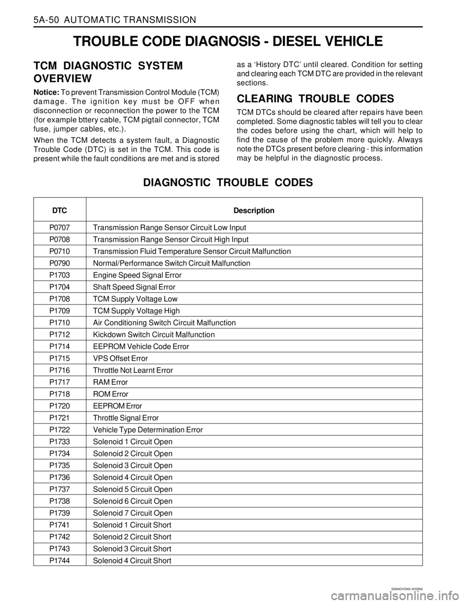
Transmission Range Sensor Circuit Low Input
Transmission Range Sensor Circuit High Input
Transmission Fluid Temperature Sensor Circuit Malfunction
Normal/Performance Switch Circuit Malfunction
Engine Speed Signal Error
Shaft Speed Signal Error
TCM Supply Voltage Low
TCM Supply Voltage High
Air Conditioning Switch Circuit Malfunction
Kickdown Switch Circuit Malfunction
EEPROM Vehicle Code Error
VPS Offset Error
Throttle Not Learnt Error
RAM Error
ROM Error
EEPROM Error
Throttle Signal Error
Vehicle Type Determination Error
Solenoid 1 Circuit Open
Solenoid 2 Circuit Open
Solenoid 3 Circuit Open
Solenoid 4 Circuit Open
Solenoid 5 Circuit Open
Solenoid 6 Circuit Open
Solenoid 7 Circuit Open
Solenoid 1 Circuit Short
Solenoid 2 Circuit Short
Solenoid 3 Circuit Short
Solenoid 4 Circuit Short
TROUBLE CODE DIAGNOSIS - DIESEL VEHICLE
TCM DIAGNOSTIC SYSTEM
OVERVIEW
Notice: To prevent Transmission Control Module (TCM)
damage. The ignition key must be OFF when
disconnection or reconnection the power to the TCM
(for example bttery cable, TCM pigtail connector, TCM
fuse, jumper cables, etc.).
When the TCM detects a system fault, a Diagnostic
Trouble Code (DTC) is set in the TCM. This code is
present while the fault conditions are met and is storedas a ‘History DTC’ until cleared. Condition for setting
and clearing each TCM DTC are provided in the relevant
sections.CLEARING TROUBLE CODES
TCM DTCs should be cleared after repairs have been
completed. Some diagnostic tables will tell you to clear
the codes before using the chart, which will help to
find the cause of the problem more quickly. Always
note the DTCs present before clearing - this information
may be helpful in the diagnostic process.
DIAGNOSTIC TROUBLE CODES
DTC
P0707
P0708
P0710
P0790
P1703
P1704
P1708
P1709
P1710
P1712
P1714
P1715
P1716
P1717
P1718
P1720
P1721
P1722
P1733
P1734
P1735
P1736
P1737
P1738
P1739
P1741
P1742
P1743
P1744Description
Page 1343 of 2053
MANUAL TRANSMISSION 5B-35
SSANGYONG MY2002
6. Remove the 2nd speed gear, bearing and spacer.
YAD5B880
YAD5B890
YAD5B910
YAD5B900
7. Using a screwdriver, remove the spiral retaining
ring.
8. Remove the thrust washer and three-piece 2nd
speed blocking ring assembly.
9. For correct reassembly, place an alignment mark
on the 1-2 synchronizer hub and sleeve.
10. Remove the 1-2 synchronizer sleeve from the hub
with following parts :
The anti-rattle ball and spring.
The three keys.
One of the 3 springs.
Page 1345 of 2053

MANUAL TRANSMISSION 5B-37
SSANGYONG MY2002
YAD5B960
YAD5B970
YAD5B990
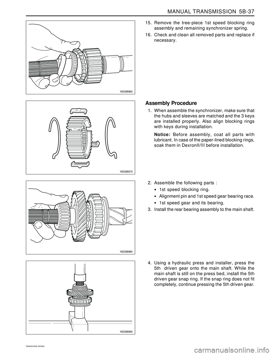
15. Remove the tree-piece 1st speed blocking ring
assembly and remaining synchronizer spring.
16. Check and clean all removed parts and replace if
necessary.
Assembly Procedure
1. When assemble the synchronizer, make sure that
the hubs and sleeves are matched and the 3 keys
are installed properly. Also align blocking rings
with keys during installation.
Notice: Before assembly, coat all parts with
lubricant. In case of the paper-lined blocking rings,
soak them in DexronII/III before installation.
2. Assemble the following parts :
1st speed blocking ring.
Alignment pin and 1st speed gear bearing race.
1st speed gear and its bearing.
3. Install the rear bearing assembly to the main shaft.
YAD5B980
4. Using a hydraulic press and installer, press the
5th driven gear onto the main shaft. While the
main shaft is still on the press bed, install the 5th
driven gear snap ring. If the snap ring does not fit
completely, continue pressing the 5th driven gear.