Page 1854 of 2053
REMOTE KEYLESS ENTRY AND ANTI-THEFT SYSTEM 9T1-7
SSANGYONG MY2002
SCHEMATIC AND ROUTING DIAGRAMS
STICS - STICS UNIT
KAA9T070
Page 1855 of 2053
SSANGYONG MY2002
9T1-8 REMOTE KEYLESS ENTRY AND ANTI-THEFT SYSTEM
STICS - DOOR CONTACT SWITCH
KAA9T080
Page 1856 of 2053
REMOTE KEYLESS ENTRY AND ANTI-THEFT SYSTEM 9T1-9
SSANGYONG MY2002
STICS - KEYLESS, KEY REMINDER SWITCH, SIREN, CHIME BELL BUZZER
KAA9T090
Page 1858 of 2053

SSANGYONG MY2002
9T2-2 IMMOBILIZER SYSTEM
DESCRIPTION AND OPERATION
Immobilizer is a device disabling vehicle ignition unless
a speific key is used and designed to help prevent
vehicle theft.
Immobilizer is comprised of two devices, a key with
encoded transponder and engine control unit (ECU)
with the same encoding of the transponder. When a
key is inserted into the key hole to start vehicle and
turned to ‘ON’, the ECU reads and decodes the
transponder code and, if the same, starts the engine,
it is called immobilizer. It means immobilizer system
disables starting by stopping fuel supply if the code
in the transponder does not match the code stored in
ECU each other.
Notice:
If vehicle is equipped with immobilizer system and
the engine cranks normally but not start, check
immobilizer system first rather than ignition and
other electrical systems because it can be
disabled fuel supply of injectors by ECU due to
defective immobilizer system.
Programming of the immobilizer system will be
performed by authorized personnel only. If
following defective codes for immobilizer system
appear during diagnosis of vehicle with SCANNER,
ask immobilizer programming to authorized
personnel and actual programming should be
performed by authorized per-sonnel only.
Display of defectives relevant to immobilizer
system : SCANNER
1. No communication with transponder
2. No immobilizer programming
The transponder in the key can be damaged by
shocks of dropping or hitting other objectives, so
handle it with care.
Each supplied key has programming of code on
its own. Accordingly if ECU needs to be replaced,
replace the transponder in the key.
The vehicle equipped with immobilizer system will
never be started with remote ignition device, so
do not attempt to install it.
The immobilizer system will never be removed from
the vehicle. So never attempt to remove it to install
a remote ignition device or others.
If engine does not start during service, use every
key to start the engine and then check immobilizer
sys-tem finally.
Cases that requires immobilizer
programming
1. Replacement ECU
In this case, replace the every transponder of the
key at once.
2. Replacement of the transponder
3. Additional key for lost 1 or 2 keys
1) Clear all codes for current keys from the ECU
2) When using current key : clear code of the trans-
ponder and re-program it
3) Additional (purchased) key : perform programming
4. When lost all keys
1) Clear all memorized key codes from the ECU
2) Replace the key and key set
3) Immobilizer programming
Page 1859 of 2053
IMMOBILIZER SYSTEM 9T2-3
SSANGYONG MY2002
COMPONENTS LOCATOR
IMMOBILIZER SYSTEM
KAA9T100
1. Immobilizer Antenna
2. Key3. Transponder
Page 1860 of 2053
SSANGYONG MY2002
9T2-4 IMMOBILIZER SYSTEM
KAA9T130
KAA9T110
ON-VEHICLE SERVICE
UNIT REPAIR
IMMOBILIZER ANTENNA
Removal and Installation Procedure
1. Remove the combination switch upper and lower
cover. Refer to Section 6E, Steering Wheel and
colmun.
2. Remove the immobilizer antenna.
3. Installation should follow the removal procedure
in the reverse order.
REPAIR INSTRUCTIONS
TRANSPONDER REPLACEMENT
Removal Procedure
1. Open the cover on key handle.
2. Remove the small screw in symmetrical position
of key illumination.
3. Remove the cover.
KAA9T120
4. Remove the transponder. Carefully remove the old
shock absorbing sealant with a razor blade if
applied.
5. Replace the transponder with new one, and apply
the small amount of shock absorbing sealant.
6. Installation should follow the removal procedure
in the reverse order.
7. Installation should follow the removal procedure
in the reverse order.
Page 1871 of 2053

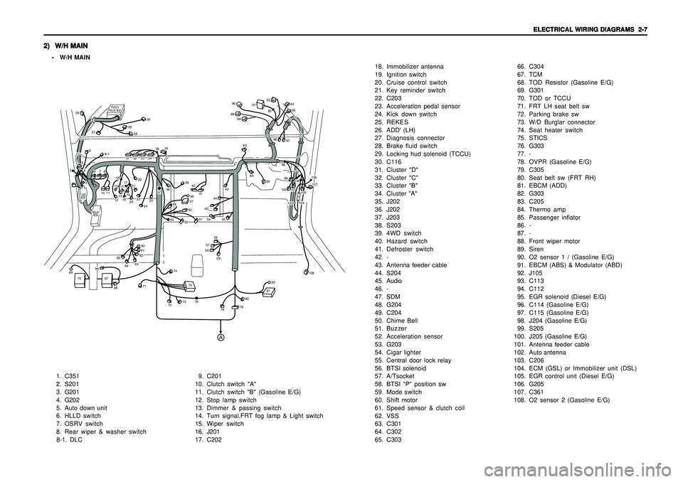
ELECTRICAL WIRING DIAGRAMS ELECTRICAL WIRING DIAGRAMSELECTRICAL WIRING DIAGRAMS ELECTRICAL WIRING DIAGRAMS
ELECTRICAL WIRING DIAGRAMS
2-7 2-7 2-7 2-7
2-7
2) 2)2) 2)
2)
W/H MAIN W/H MAINW/H MAIN W/H MAIN
W/H MAIN• W/H MAIN
1. C351
2. S201
3. G201
4. G202
5. Auto down unit
6. HLLD switch
7. OSRV switch
8. Rear wiper & washer switch
8-1. DLC9. C201
10. Clutch switch "A"
11. Clutch switch "B" (Gasoline E/G)
12. Stop lamp switch
13. Dimmer & passing switch
14. Turn signal,FRT fog lamp & Light switch
15. Wiper switch
16. J201
17. C20218. Immobilizer antenna
19. Ignition switch
20. Cruise control switch
21. Key reminder switch
22. C203
23. Acceleration pedal sensor
24. Kick down switch
25. REKES
26. ADD' (LH)
27. Diagnosis connector
28. Brake fluid switch
29. Locking hud solenoid (TCCU)
30. C116
31. Cluster "D"
32. Cluster "C"
33. Cluster "B"
34. Cluster "A"
35. J202
36. J202
37. J203
38. S203
39. 4WD switch
40. Hazard switch
41. Defroster switch
42. -
43. Antenna feeder cable
44. S204
45. Audio
46. -
47. SDM
48. G204
49. C204
50. Chime Bell
51. Buzzer
52. Acceleration sensor
53. G203
54. Cigar lighter
55. Central door lock relay
56. BTSI solenoid
57. A/Tsocket
58. BTSI "P" position sw
59. Mode switch
60. Shift motor
61. Speed sensor & clutch coil
62. VSS
63. C301
64. C302
65. C30366. C304
67. TCM
68. TOD Resistor (Gasoline E/G)
69. G301
70. TOD or TCCU
71. FRT LH seat belt sw
72. Parking brake sw
73. W/D Burglar connector
74. Seat heater switch
75. STICS
76. G303
77. -
78. OVPR (Gasoline E/G)
79. C305
80. Seat belt sw (FRT RH)
81. EBCM (ADD)
82. G303
83. C205
84. Thermo amp
85. Passenger inflator
86. -
87. -
88. Front wiper motor
89. Siren
90. O2 sensor 1 / (Gasoline E/G)
91. EBCM (ABS) & Modulator (ABD)
92. J105
93. C113
94. C112
95. EGR solenoid (Diesel E/G)
96. C114 (Gasoline E/G)
97. C115 (Gasoline E/G)
98. J204 (Gasoline E/G)
99. S205
100.J205 (Gasoline E/G)
101.Antenna feeder cable
102.Auto antenna
103.C206
104.ECM (GSL) or Immobilizer unit (DSL)
105.EGR control unit (Diesel E/G)
106. G205
107.C361
108. O2 sensor 2 (Gasoline E/G)
FUSE
BOX
RELAY
BOX
FUSE &
RELAY BOX
A
1011
12131415171618192021222829
30
26
27
31323334
35
3637
38
394041
43
83888990
91
93
9495
9296
979899102
101100
106107
104105
103
108
84
85
44
8-1
4748
49
50
51
52
53
45
55
54565758
60616263
6465
66
67
68
71
72
73
74
7576
78
7980
8182
69
70
59
232425
13
4259678
Page 1874 of 2053
2-10 2-10 2-10 2-10
2-10
ELECTRICAL WIRING DIAGRAMS ELECTRICAL WIRING DIAGRAMSELECTRICAL WIRING DIAGRAMS ELECTRICAL WIRING DIAGRAMS
ELECTRICAL WIRING DIAGRAMS5) 5)5) 5)
5)
W/H DOOR W/H DOORW/H DOOR W/H DOOR
W/H DOOR
1. Door actuator
2. Door key cylinder switch
3. Power window switch
4. OSRV mirror motor
5. Power window motor
6. C352 (FRONT LH),C362(FRONT RH)
7. C351 (FRONT LH),C361(FRONT RH)
8. Speaker
9. Courtesy lamp
6) 6)6) 6)
6)
W/H TAIL GATE W/H TAIL GATEW/H TAIL GATE W/H TAIL GATE
W/H TAIL GATE
1. Rear washer motor
2. Tail gate door lock actuator
3. C403 (soft top)
4. Tail gate key cylinder sw
5. Rear heated glass
6. Rear wiper motor
7. Rear heated glass
8. C402
9. C401