Page 588 of 1399

−
DIAGNOSTICS AUTOMATIC TRANSMISSION
DI−151
1996 LAND CRUISER (RM451U)
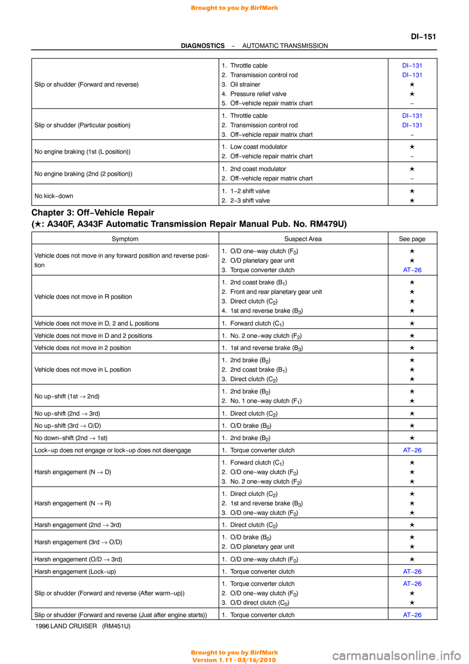
Slip or shudder (Forward and reverse)
1. Throttle cable
2. Transmission control rod
3. Oil strainer
4. Pressure relief valve
5. Off
−vehicle repair matrix chartDI−131
DI−131
�
�−
Slip or shudder (Particular position)
1. Throttle cable
2. Transmission control rod
3. Off −vehicle repair matrix chartDI−131
DI−131
−
No engine braking (1st (L position))1. Low coast modulator
2. Off −vehicle repair matrix chart�
−
No engine braking (2nd (2 position))1. 2nd coast modulator
2. Off −vehicle repair matrix chart�
−
No kick− down1. 1−2 shift valve
2. 2 −3 shift valve�
�
Chapter 3: Off −Vehicle Repair
( � : A340F, A343F Automatic Transmission Repair Manual Pub. No. RM479U)
SymptomSuspect AreaSee page
Vehicle does not move in any forward position and reverse posi-
tion1. O/D one− way clutch (F0)
2. O/D planetary gear unit
3. Torque converter clutch�
�
AT −26
Vehicle does not move in R position
1. 2nd coast brake (B1)
2. Front and rear planetary gear unit
3. Direct clutch (C
2)
4. 1st and reverse brake (B
3)
�
�
�
�
Vehicle does not move in D, 2 and L positions1. Forward clutch (C1)�
Vehicle does not move in D and 2 positions1. No. 2 one− way clutch (F2)�
Vehicle does not move in 2 position1. 1st and reverse brake (B3)�
Vehicle does not move in L position
1. 2nd brake (B2)
2. 2nd coast brake (B
1)
3. Direct clutch (C
2)
�
�
�
No up− shift (1st → 2nd)1. 2nd brake (B2)
2. No. 1 one− way clutch (F
1)
�
�
No up−shift (2nd → 3rd)1. Direct clutch (C2)�
No up−shift (3rd → O/D)1. O/D brake (B0)�
No down−shift (2nd → 1st)1. 2nd brake (B2)�
Lock−up does not engage or lock −up does not disengage1. Torque converter clutchAT −26
Harsh engagement (N → D)
1. Forward clutch (C1)
2. O/D one− way clutch (F
0)
3. No. 2 one− way clutch (F
2)
�
�
�
Harsh engagement (N → R)
1. Direct clutch (C2)
2. 1st and reverse brake (B
3)
3. O/D one− way clutch (F
0)
�
�
�
Harsh engagement (2nd → 3rd)1. Direct clutch (C2)�
Harsh engagement (3rd → O/D)1. O/D brake (B0)
2. O/D planetary gear unit�
�
Harsh engagement (O/D → 3rd)1. O/D one− way clutch (F0)�
Harsh engagement (Lock −up)1. Torque converter clutchAT −26
Slip or shudder (Forward and reverse (After warm −up))
1. Torque converter clutch
2. O/D one− way clutch (F
0)
3. O/D direct clutch (C
0)
AT −26
�
�
Slip or shudder (Forward and reverse (Just after engine starts))1. Torque converter clutchAT −26
Brought to you by BirfMark
Brought to you by BirfMark
Version 1.11 - 03/16/2010
Page 589 of 1399

DI−152
−
DIAGNOSTICS AUTOMATIC TRANSMISSION
1996 LAND CRUISER (RM451U)
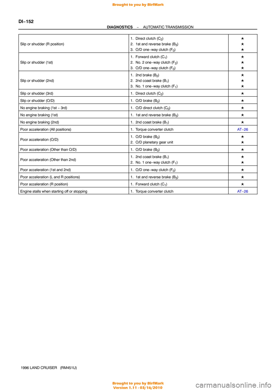
Slip or shudder (R position)
1. Direct clutch (C2)
2. 1st and reverse brake (B
3)
3. O/D one− way clutch (F
0)
�
�
�
Slip or shudder (1st)
1. Forward clutch (C1)
2. No. 2 one− way clutch (F
2)
3. O/D one− way clutch (F
0)
�
�
�
Slip or shudder (2nd)
1. 2nd brake (B2)
2. 2nd coast brake (B
1)
3. No. 1 one− way clutch (F
1)
�
�
�
Slip or shudder (3rd)1. Direct clutch (C2)�
Slip or shudder (O/D)1. O/D brake (B0)�
No engine braking (1st − 3rd)1. O/D direct clutch (C0)�
No engine braking (1st)1. 1st and reverse brake (B3)�
No engine braking (2nd)1. 2nd coast brake (B1)�
Poor acceleration (All positions)1. Torque converter clutchAT −26
Poor acceleration (O/D)1. O/D brake (B0)
2. O/D planetary gear unit�
�
Poor acceleration (Other than O/D)1. O/D brake (B0)�
Poor acceleration (Other than 2nd)1. 2nd coast brake (B1)
2. No. 1 one− way clutch (F
1)
�
�
Poor acceleration (1st and 2nd)1. O/D one−way clutch (F0)�
Poor acceleration (L and R positions)1. 1st and reverse brake (B3)�
Poor acceleration (R position)1. Forward clutch (C1)�
Engine stalls when starting off or stopping1. Torque converter clutchAT−26
Brought to you by BirfMark
Brought to you by BirfMark
Version 1.11 - 03/16/2010
Page 598 of 1399

D00076
Line
PressureDrain
Q08219
Q08226
D00087
(+)
(−)
(+)(−)
Air
−
DIAGNOSTICS AUTOMATIC TRANSMISSION
DI−161
1996 LAND CRUISER (RM451U)
DTC P0770 Shift Solenoid E Malfunction
(Shift Solenoid Valve SL)
SYSTEM DESCRIPTION
The ECM uses the signals from the throttle position sensor, air −
flow meter and crankshaft position sensor to monitor the en-
gagement condition of the lock −up clutch.
Then the ECM compares the engagement condition of the
lock−up clutch with the lock −up schedule in the ECM memory
to detect mechanical trouble of the shift solenoid valve SL,
valve body and torque converter clutch.
DTC No.DTC Detecting ConditionTrouble Area
P0770
Lock− up does not occur when driving in the lock− up range
(normal driving at 80 km/h [50 mph] ), or lock− up remains ON
in the lock− up OFF range (2 trip detection logic)�Shift solenoid valve SL is stuck open or closed
� Valve body blocked up or stuck
� Lock− up clutch
INSPECTION PROCEDURE
1 Check shift solenoid valve SL operation.
PREPARATION:
Remove the shift solenoid valve SL from the valve body.
CHECK:
(a) Applying 490 kPa (5 kgf/cm2, 71 psi) of compressed air,
check that the solenoid valve opens.
(b) When battery voltage is supplied to the shift solenoid
valve, check it does not leak air.
NG Replace shift solenoid valve SL.
OK
DI5KQ−02
Brought to you by BirfMark
Brought to you by BirfMark
Version 1.11 - 03/16/2010
Page 599 of 1399
DI−162
−
DIAGNOSTICS AUTOMATIC TRANSMISSION
1996 LAND CRUISER (RM451U)
2 Check valve body (See page DI−147 ).
NG Repair or replace valve body.
OK
Replace torque converter clutch (See page
AT −26 ).
Brought to you by BirfMark
Brought to you by BirfMark
Version 1.11 - 03/16/2010
Page 777 of 1399

−
EMISSION CONTROL EVAPORATIVE EMISSION (EVAP) CONTROL SYSTEM
EC−7
1996 LAND CRUISER (RM451U)
9. VISUALLY INSPECT CHARCOAL CANISTER
Look for cracks or damage.
10. INSPECT FOR CLOGGED FILTER AND STUCK VALVE
(a) Using low pressure compressed air (7.26 kPa, 74 gf/cm
2,
1.05 psi), blow into tank pipe and check that air flows with-
out resistance from the other pipes.
(b) While holding drain pipe closed, blow air (1.96 kPa, 20 gf/
cm
2, 0.28 psi) into purge pipe and check that air flow with-
out resistance from tank pipe.
If a problem is found, replace the charcoal canister.
11. CLEAN FILTER IN CANISTER
Clean the filter by blowing 294 kPa (3 kgf/cm
2, 43 psi) of com-
pressed air into tank pipe while holding purge pipe closed.
NOTICE:
Do not attempt to wash the canister.No activated carbon
should come out.
12. REINSTALL CAP TO CHARCOAL CANISTER
13. REINSTALL CHARCOAL CANISTER TO BRACKET Torque: 14 N·m (145 kgf·cm, 10 ft·lbf)
14. REINSTALL CHARCOAL CANISTER WITH BRACKET Torque: 18 N·m (185 kgf·cm, 13 ft·lbf)
15. DRAIN ENGINE COOLANT
Brought to you by BirfMark
Brought to you by BirfMark
Version 1.11 - 03/16/2010
Page 778 of 1399
EC−8
−
EMISSION CONTROL EVAPORATIVE EMISSION (EVAP) CONTROL SYSTEM
1996 LAND CRUISER (RM451U)
16. REMOVE TVV FROM CYLINDER HEAD
(a) Disconnect the 2 vacuum hoses.
(b) Remove the TVV.
17. INSPECT TVV OPERATION
(a) Cool the TVV to below 45° C (113°F) with cool water.
(b) Check that air flows from pipe J to the air filter.
(c) Heat the TVV to above 64° C (147°F) with hot water.
(d) Check that air flows from pipe J to pipe K.
If operation is not as specified, replace the TVV.
18. REINSTALL TVV
(a) Apply adhesive to 2 or 3 threads of the TVV, and install it.
Adhesive:
Part No. 08833 −00070, THREE BOND 1324
or equivalent
Torque: 29 N·m (300 kgf·cm, 22 ft·lbf)
(b) Reconnect 2 vacuum hoses.
19. REFILL WITH ENGINE COOLANT
20. REMOVE INTAKE MANIFOLD STAY
21. REMOVE VCV
Brought to you by BirfMark
Brought to you by BirfMark
Version 1.11 - 03/16/2010
Page 779 of 1399

EC0107
Orange PipeBlack Pipe
−
EMISSION CONTROL EVAPORATIVE EMISSION (EVAP) CONTROL SYSTEM
EC−9
1996 LAND CRUISER (RM451U)
22. INSPECT VCV
(a) Apply vacuum above 9.3 kPa (70 mmHg, 2.76 in.Hg) to
pipe S.
(b) Blow air into pipe Y and check that air comes out of pipe Z.
(c) Stop the applied vacuum.
(d) Blow air into pipe Y and check that air does not come out
of pipe Z.
If operation is not as specified, replace the VCV.
23. REINSTALL VCV
24. INSTALL INTAKE MANIFOLD STAY Torque: 36 N·m (360 kgf·cm, 26 ft·lbf)
25. REMOVE INTAKE MANIFOLD STAY
26. REMOVE CHECK VALVE
27. INSPECT CHECK VALVE
(a) Check that air flows from the orange pipe to the black pipe.
(b) Check that air does not flow from the black pipe to the
orange pipe.
If operation is not as specified, replace the check valve.
28. REINSTALL CHECK VALVE
HINT:
Reinstall the check valve with the black pipe facing the VCV
side.
29. INSTALL INTAKE MANIFOLD STAY Torque: 36 N·m (360 kgf·cm, 26 ft·lbf)
Brought to you by BirfMark
Brought to you by BirfMark
Version 1.11 - 03/16/2010
Page 784 of 1399

EC−14
−
EMISSION CONTROL EXHAUST GAS RECIRCULATION (EGR) SYSTEM
1996 LAND CRUISER (RM451U)
21. REMOVE EGR VACUUM MODULATOR
22. REMOVE EGR VALVE
(a) Disconnect the vacuum hose from the EGR valve.
(b) Disconnect the engine wire from the clamp.
(c) Loosen the EGR pipe union nut.
(d) Remove the 2 nuts holding the EGR valve to the air intake
chamber.
(e) Using 2 nuts, remove the 2 stud bolts, EGR valve and gasket.
23. INSPECT EGR VALVE
Check for sticking and heavy carbon deposits.
If a problem is found, replace the valve.
24. REINSTALL EGR VALVE
(a) Using 2 nuts, temporarily install a new gasket, and EGR valve with the 2 stud bolts.
Torque: 9 N·m (90 kgf·cm, 78 in.·lbf)
(b) Install the 2 nuts holding the EGR valve to the air intake
chamber.
Torque: 18 N·m (180 kgf·cm, 13 ft·lbf)
(c) Tighten the union nut of the EGR pipe. Torque: 64 N·m (650 kgf·cm, 47 ft·lbf)
(d) Connect the engine wire to the clamp.
(e) Connect the vacuum hose to the EGR valve.
25. REINSTALL EGR VACUUM MODULATOR
Torque: 18 N·m (185 kgf·cm, 13 ft·lbf)
Brought to you by BirfMark
Brought to you by BirfMark
Version 1.11 - 03/16/2010