Page 861 of 1399

EM1EE−02
EM−76
−
ENGINE MECHANICAL ENGINE UNIT
1996 LAND CRUISER (RM451U)
INSTALLATION
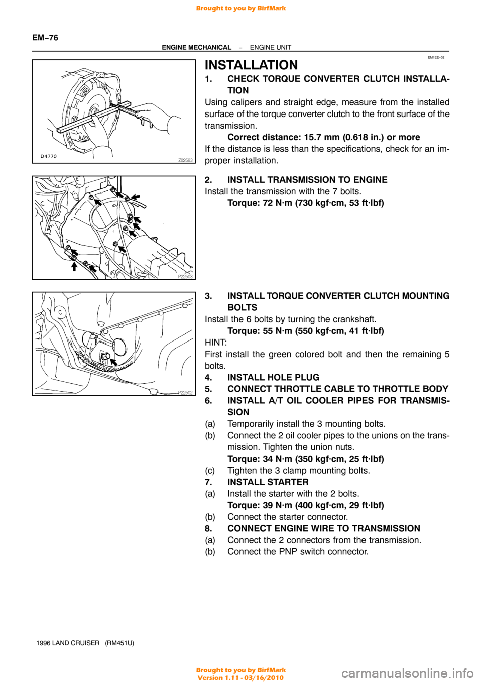
1. CHECK TORQUE CONVERTER CLUTCH INSTALLA- TION
Using calipers and straight edge, measure from the installed
surface of the torque converter clutch to the front surface of the
transmission. Correct distance: 15.7 mm (0.618 in.) or more
If the distance is less than the specifications, check for an im-
proper installation.
2. INSTALL TRANSMISSION TO ENGINE
Install the transmission with the 7 bolts. Torque: 72 N·m (730 kgf·cm, 53 ft·lbf)
3. INSTALL T ORQUE CONVERTER CLUTCH MOUNTING
BOLTS
Install the 6 bolts by turning the crankshaft. Torque: 55 N·m (550 kgf·cm, 41 ft·lbf)
HINT:
First install the green colored bolt and then the remaining 5
bolts.
4. INSTALL HOLE PLUG
5. CONNECT THROTTLE CABLE TO THROTTLE BODY
6. INSTALL A/T OIL COOLER PIPES FOR TRANSMIS-
SION
(a) Temporarily install the 3 mounting bolts.
(b) Connect the 2 oil cooler pipes to the unions on the trans-
mission. Tighten the union nuts.
Torque: 34 N·m (350 kgf·cm, 25 ft·lbf)
(c) Tighten the 3 clamp mounting bolts.
7. INSTALL STARTER
(a) Install the starter with the 2 bolts. Torque: 39 N·m (400 kgf·cm, 29 ft·lbf)
(b) Connect the starter connector.
8. CONNECT ENGINE WIRE TO TRANSMISSION
(a) Connect the 2 connectors from the transmission.
(b) Connect the PNP switch connector.
Brought to you by BirfMark
Brought to you by BirfMark
Version 1.11 - 03/16/2010
Page 862 of 1399

−
ENGINE MECHANICAL ENGINE UNIT
EM−77
1996 LAND CRUISER (RM451U)
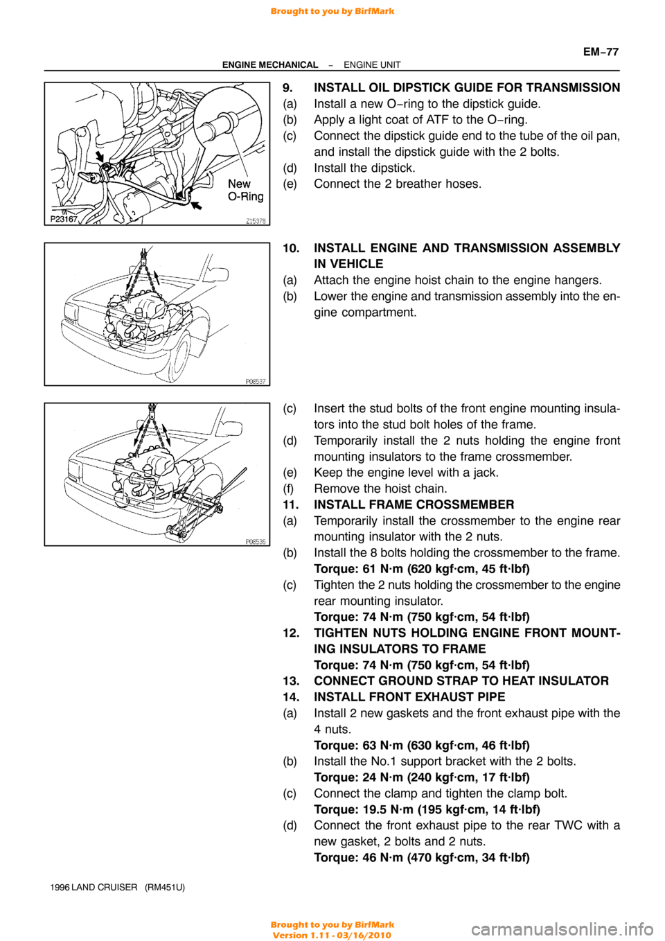
9. INSTALL OIL DIPSTICK GUIDE FOR TRANSMISSION
(a) Install a new O−ring to the dipstick guide.
(b) Apply a light coat of ATF to the O −ring.
(c) Connect the dipstick guide end to the tube of the oil pan, and install the dipstick guide with the 2 bolts.
(d) Install the dipstick.
(e) Connect the 2 breather hoses.
10. INSTALL ENGINE AND TRANSMISSION ASSEMBLY IN VEHICLE
(a) Attach the engine hoist chain to the engine hangers.
(b) Lower the engine and transmission assembly into the en-
gine compartment.
(c) Insert the stud bolts of the front engine mounting insula- tors into the stud bolt holes of the frame.
(d) Temporarily install the 2 nuts holding the engine front mounting insulators to the frame crossmember.
(e) Keep the engine level with a jack.
(f) Remove the hoist chain.
11. INSTALL FRAME CROSSMEMBER
(a) Temporarily install the crossmember to the engine rear mounting insulator with the 2 nuts.
(b) Install the 8 bolts holding the crossmember to the frame. Torque: 61 N·m (620 kgf·cm, 45 ft·lbf)
(c) Tighten the 2 nuts holding the crossmember to the engine
rear mounting insulator.
Torque: 74 N·m (750 kgf·cm, 54 ft·lbf)
12. TIGHTEN NUTS HOLDING ENGINE FRONT MOUNT- ING INSULATORS TO FRAME
Torque: 74 N·m (750 kgf·cm, 54 ft·lbf)
13. CONNECT GROUND STRAP TO HEAT INSULATOR
14. INSTALL FRONT EXHAUST PIPE
(a) Install 2 new gaskets and the front exhaust pipe with the
4 nuts.
Torque: 63 N·m (630 kgf·cm, 46 ft·lbf)
(b) Install the No.1 support bracket with the 2 bolts.
Torque: 24 N·m (240 kgf·cm, 17 ft·lbf)
(c) Connect the clamp and tighten the clamp bolt. Torque: 19.5 N·m (195 kgf·cm, 14 ft·lbf)
(d) Connect the front exhaust pipe to the rear TWC with a
new gasket, 2 bolts and 2 nuts.
Torque: 46 N·m (470 kgf·cm, 34 ft·lbf)
Brought to you by BirfMark
Brought to you by BirfMark
Version 1.11 - 03/16/2010
Page 863 of 1399
EM−78
−
ENGINE MECHANICAL ENGINE UNIT
1996 LAND CRUISER (RM451U)
15. INSTALL TRANSFER SHIFT LEVER
(a) Install the shift lever and hose clamp with the 4 bolts.
Torque: 18 N·m (185 kgf·cm, 13 ft·lbf)
(b) Connect the shift rod and install the pin.
(c) Install the transfer shift lever boot and transmission shift lever assembly with the 10 bolts.
Torque: 5.4 N·m (55 kgf·cm, 48 in.·lbf)
(d) Connect the 3 connectors to the transmission shift lever assembly.
(e) Install the console box with the 3 bolts.
(f) Connect the pattern select switch connector.
(g) Install the console with the 4 screws.
(h) Install the transfer shift lever knob.
(i) Shift the shift lever to N position.
(j) Fully turn the control shaft lever back and return 2 notches. It is now in neutral position.
(k) Connect the transmission control rod with the nut.
Torque: 13 N·m (130 kgf·cm, 9 ft·lbf)
Brought to you by BirfMark
Brought to you by BirfMark
Version 1.11 - 03/16/2010
Page 864 of 1399

−
ENGINE MECHANICAL ENGINE UNIT
EM−79
1996 LAND CRUISER (RM451U)
16. Differential Side:
INSTALL FRONT AND REAR PROPELLER SHAFTS
(a) Align the matchmarks on the flanges and connect the
flanges with the 4 bolts and nuts.
(b) Torque the bolts and nuts. Torque:
74 N·m (750 kgf·cm, 54 ft·lbf) for front shaft
88 N·m (900 kgf·cm, 65 ft·lbf)for rear shaft
17. Transfer Side: INSTALL FRONT AND REAR PROPELLER SHAFTS
(a) Align the matchmarks on the flanges and connect the flanges with the 4 nuts.
(b) Torque the nuts. Torque:
74 N·m (750 kgf·cm, 54 ft·lbf) for front shaft
88 N·m (900 kgf·cm, 65 ft·lbf) for rear shaft
18. INSTALL STABILIZER BAR
(a) Temporarily install the stabilizer bar to the axle housing with the bolt and nut.
(b) Connect the stabilizer bar with the 2 bolts. Torque: 18 N·m (185 kgf·cm, 13 ft·lbf)
(c) Bounce the vehicle up and down to stabilize the suspen- sion.
(d) Torque the bolt and nut holding the stabilizer bar to the axle housing.
Torque: 25 N·m (260 kgf·cm, 19 ft·lbf)
Brought to you by BirfMark
Brought to you by BirfMark
Version 1.11 - 03/16/2010
Page 865 of 1399

EM−80
−
ENGINE MECHANICAL ENGINE UNIT
1996 LAND CRUISER (RM451U)
19. CONNECT ENGINE WIRE TO CABIN
(a) Push in the engine wire through the cowl panel.
(b) Connect the connectors.
(1) Connect the 3 connectors to the ECM.
(2) Connect the 2 connectors to the cowl wire.
(c) Connect the A/C amplifier with the screw.
(d) Install the speaker panel with the screw.
(e) Install the glove compartment door with the 2 screws.
20. CONNECT PS RETURN HOSE
Connect the return hose to the PS reservoir tank.
21. CONNECT PS PRESSURE HOSE
Connect the PS pressure hose with 2 new gaskets and the
union bolt. Torque: 56 N·m (575 kgf·cm, 42 ft·lbf)
22. INSTALL RADIATOR PIPE
(a) Connect the No. 2 radiator hose to the water inlet.
(b) Install the 2 nuts holding the radiator pipe to the No. 1 oil pan.
Torque: 21 N·m (210 kgf·cm, 15 ft·lbf)
23. INSTALL A/C COMPRESSOR AND BRACKET
(a) Install the A/C compressor bracket with the 5 bolts.
Torque: 37 N·m (375 kgf·cm, 27 ft·lbf)
(b) Install the A/C compressor with the 4 bolts. Torque: 25 N·m (250 kgf·cm, 18 ft·lbf)
(c) Install and adjust the drive belt (See page CH−2).
24. CONNECT WIRES AND CONNECTORS
(a) Connect the 2 heated oxygen sensor connectors.
(b) Connect the DLC1 clamp.
(c) Connect the 2 oil pressure gauge connectors.
(d) Connect the generator wire and connector.
(e) Connect the connector on the intake manifold to the fend-
er apron.
(f) Connect the high −tension cord to the ignition coil.
(g) Connect the ground strap to the No. 1 engine hanger.
(h) Connect the ground strap to the air intake chamber.
(i) Connect the starter wire.
(j) Connect the ground cable to the cylinder block.
25. CONNECT FUEL HOSES
(a) Connect the fuel inlet hose to the fuel filter with 2 new gas-
kets and the union bolt.
Torque: 29 N·m (300 kgf·cm, 22 ft·lbf)
(b) Connect the fuel return hose.
Brought to you by BirfMark
Brought to you by BirfMark
Version 1.11 - 03/16/2010
Page 889 of 1399
EM−104
−
ENGINE MECHANICAL CYLINDER BLOCK
1996 LAND CRUISER (RM451U)
(c) Position the piston rings so that the ring ends are as shown.
NOTICE:
Do not align the ring ends.
3. INSTALL BEARINGS
(a) Align the bearing claw with the groove of the connecting
rod or connecting rod cap.
(b) Install the bearings in the connecting rod and connecting rod cap.
4. INSTALL CYLINDER BLOCK ORIFICE
5. INSTALL OIL NOZZLES AND CHECK VALVES
(a) Align the pin of the oil nozzle with the pin hole of the cylin-
der block.
(b) Install the oil nozzle with the check valve. Install the 6 oil nozzles and check valves.
Torque: 25 N·m (250 kgf·cm, 18 ft·lbf)
Brought to you by BirfMark
Brought to you by BirfMark
Version 1.11 - 03/16/2010
Page 891 of 1399

EM−106
−
ENGINE MECHANICAL CYLINDER BLOCK
1996 LAND CRUISER (RM451U)
(2) Install the 7 main bearing caps in their proper loca-
tions.
HINT:
Each bearing cap has a number and front mark.
(b) Install the main bearing cap bolts.
HINT:
�The main bearing cap bolts are tightened in 2 progressive
steps (steps (b) and (d)).
�If any of the main bearing cap bolts is broken or deformed,
replace it.
(1) Apply a light coat of engine oil on the threads and
under the heads of the main bearings cap bolts.
(2) Install and uniformly tighten the 14 bolts of the main
bearing caps, in several passes, in the sequence
shown.
Torque: 74 N·m (750 kgf·cm, 54 ft·lbf)
If any one of the main bearing cap bolts does not meet the
torque specification, replace the main bearing cap bolt.
(3) Mark the front of the main bearing cap bolt withpaint.
(4) Retighten the main bearing cap bolts by 90 ° in the
numerical order shown above.
(5) Check that the painted mark is now at a 90° angle
to the front.
(c) Check that the crankshaft turns smoothly.
(d) Check that the crankshaft thrust clearance (See page EM−83 ).
10. INSTALL PISTON AND CONNECTING ROD AS- SEMBLIES
(a) Cover the connecting rod bolts with a short piece of hose
to protect the crankshaft from damage.
Brought to you by BirfMark
Brought to you by BirfMark
Version 1.11 - 03/16/2010
Page 892 of 1399

−
ENGINE MECHANICAL CYLINDER BLOCK
EM−107
1996 LAND CRUISER (RM451U)
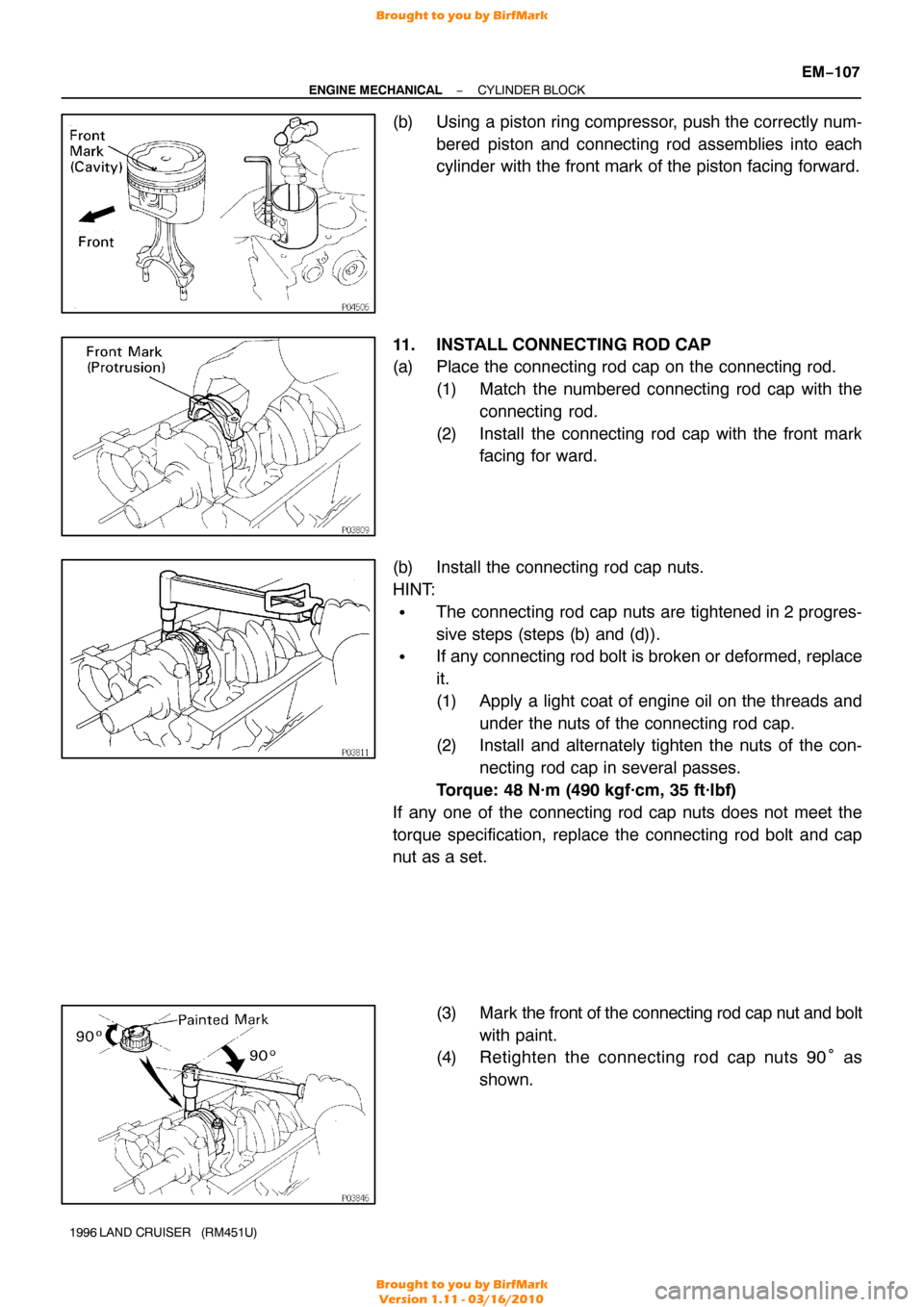
(b) Using a piston ring compressor, push the correctly num-
bered piston and connecting rod assemblies into each
cylinder with the front mark of the piston facing forward.
11. INSTALL CONNECTING ROD CAP
(a) Place the connecting rod cap on the connecting rod. (1) Match the numbered connecting rod cap with theconnecting rod.
(2) Install the connecting rod cap with the front mark facing for ward.
(b) Install the connecting rod cap nuts.
HINT:
�The connecting rod cap nuts are tightened in 2 progres-
sive steps (steps (b) and (d)).
�If any connecting rod bolt is broken or deformed, replace
it.
(1) Apply a light coat of engine oil on the threads and under the nuts of the connecting rod cap.
(2) Install and alternately tighten the nuts of the con-
necting rod cap in several passes.
Torque: 48 N·m (490 kgf·cm, 35 ft·lbf)
If any one of the connecting rod cap nuts does not meet the
torque specification, replace the connecting rod bolt and cap
nut as a set.
(3) Mark the front of the connecting rod cap nut and bolt
with paint.
(4) Retighten the connecting rod cap nuts 90 ° as
shown.
Brought to you by BirfMark
Brought to you by BirfMark
Version 1.11 - 03/16/2010