Page 675 of 1399

H00059
TerminalTime of Body Ground
Tc
Tc
ABOFF
AB
Body
GroundON
OFF
Body
Ground
”1”
”2” ”3”
”4””5”
OFF
1 second
( ± 0.5 sec.) 1 second
( ± 0.5 sec.)
Several
seconds
50 m sec.
50 m sec.
R13819
DI−242
−
DIAGNOSTICS SUPPLEMENTAL RESTRAINT SYSTEM
1996 LAND CRUISER (RM451U)
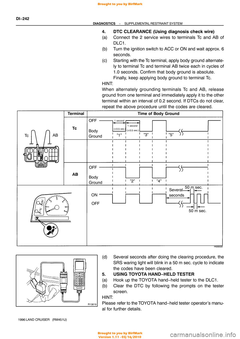
4. DTC CLEARANCE (Using diagnosis check wire)
(a) Connect the 2 service wires to terminals Tc and AB of
DLC1.
(b) Turn the ignition switch to ACC or ON and wait approx. 6 seconds.
(c) Starting with the Tc terminal, apply body ground alternate-
ly to terminal Tc and terminal AB twice each in cycles of
1.0 seconds. Confirm that body ground is absolute.
Finally, keep applying body ground to terminal Tc.
HINT:
When alternately grounding terminals Tc and AB, release
ground from one terminal and immediately apply it to the other
terminal within an interval of 0.2 second. If DTCs do not clear,
repeat the above procedure until the codes are cleared.
(d) Several seconds after doing the clearing procedure, the SRS waring light will blink in a 50 m sec. cycle to indicate
the codes have been cleared.
5. USING TOYOTA HAND−HELD TESTER
(a) Hook up the TOYOTA hand−held tester to the DLC1.
(b) Clear the DTC by following the prompts on the tester
screen.
HINT:
Please refer to the T OYOTA hand −held tester operator ’s manu-
al for further details.
Brought to you by BirfMark
Brought to you by BirfMark
Version 1.11 - 03/16/2010
Page 789 of 1399

EM1Q4−01
P05120A16078
1 Dot Mark
EM−4
−
ENGINE MECHANICAL VALVE CLEARANCE
507
Author�: Date�:
1996 LAND CRUISER (RM451U)
VALVE CLEARANCE
INSPECTION
HINT:
Inspect and adjust the valve clearance when the engine is cold.
1. DRAIN ENGINE COOLANT
2. REMOVE THROTTLE BODY (See page SF−45)
3. DISCONNECT ENGINE WIRE AND HEATER VALVE FROM COWL PANEL
(a) Remove the 2 bolts and disc onnect the ground strap and
engine wire.
(b) Remove the 2 bolts and disconnect the heater valve.
4. DISCONNECT HIGH −TENSION CORDS FROM SPARK
PLUGS (See page IG−1 )
5. REMOVE CYLINDER HEAD COVER
Remove the 13 bolts, cylinder head cover and gasket.
6. SET NO. 1 CYLINDER TO TDC/COMPRESSION
(a) Turn the crankshaft pulley, and align its groove with the timing mark ”0” of the timing chain cover.
(b) Check that the timing marks (1 and 2 dots) of the camshaft
drive and driven gears are in straight line on the cylinder
head surface as shown in the illustration.If not, turn the
crankshaft 1 revolution (360 °) and align the marks as
above.
Brought to you by BirfMark
Brought to you by BirfMark
Version 1.11 - 03/16/2010
Page 792 of 1399

EM0494
−
ENGINE MECHANICAL VALVE CLEARANCE
EM−7
510
Author�: Date�:
1996 LAND CRUISER (RM451U)
9. Rear valves of No. 6 cylinder
ADJUST VALVE CLEARANCE
(a) Remove the distributor (See page IG−10).
(b) Remove the camshafts (See page EM−28).
(c) Remove the adjusting shim with a small screwdriver.
(d) Determine the replacement adjusting shim size by follow- ing the Formula or Charts:
�Using a micrometer, measure the thickness of the
removed shim.
�Calculate the thickness of a new shim so that the
valve clearance comes within specified value.
T ....... Thickness of removed shim
A ....... Measured valve clearance
N ....... Thickness of new shim
Intake: N = T + (A − 0.20 mm (0.008 in.))
Exhaust: N = T + (A − 0.30 mm (0.012 in.))
�Select a new shim with a thickness as close as pos-
sible to the calculated value.
HINT:
Shims are available in 17 sized in increments of 0.05 mm
(0.0020 in.), from 2.50 mm (0.0984 in.) to 3.30 mm (0.1299 in.).
(e) Place a new adjusting shim on the valve lifters.
(f) Install the camshafts (See page EM−54 ).
(g) Recheck the valve clearance.
(h) Install the distributor (See page IG−11 ).
10. REINSTALL CYLINDER HEAD COVER
(a) Install the gasket to the cylinder head cover.
(b) Install the cylinder head cover with the 13 bolts.
11. RECONNECT HIGH −TENSION CORDS TO SPARK
PLUGS (See page IG−1 )
12. RECONNECT HEA TER VALVE AND ENGINE WIRE TO
COWL PANEL
(a) Connect the heater valve with the 2 bolts.
(b) Connect the ground strap and engine wire with the 2 bolts.
13. REINSTALL THROTTLE BODY (See page SF−48 )
14. REFILL RADIATOR WITH ENGINE COOLANT
15. CHECK AND ADJUST IGNITION TIMING (See page EM−10 )
Brought to you by BirfMark
Brought to you by BirfMark
Version 1.11 - 03/16/2010
Page 827 of 1399

Z00054
44.5°
EM0181
Margin Thickness
EM−42
−
ENGINE MECHANICAL CYLINDER HEAD
1996 LAND CRUISER (RM451U)
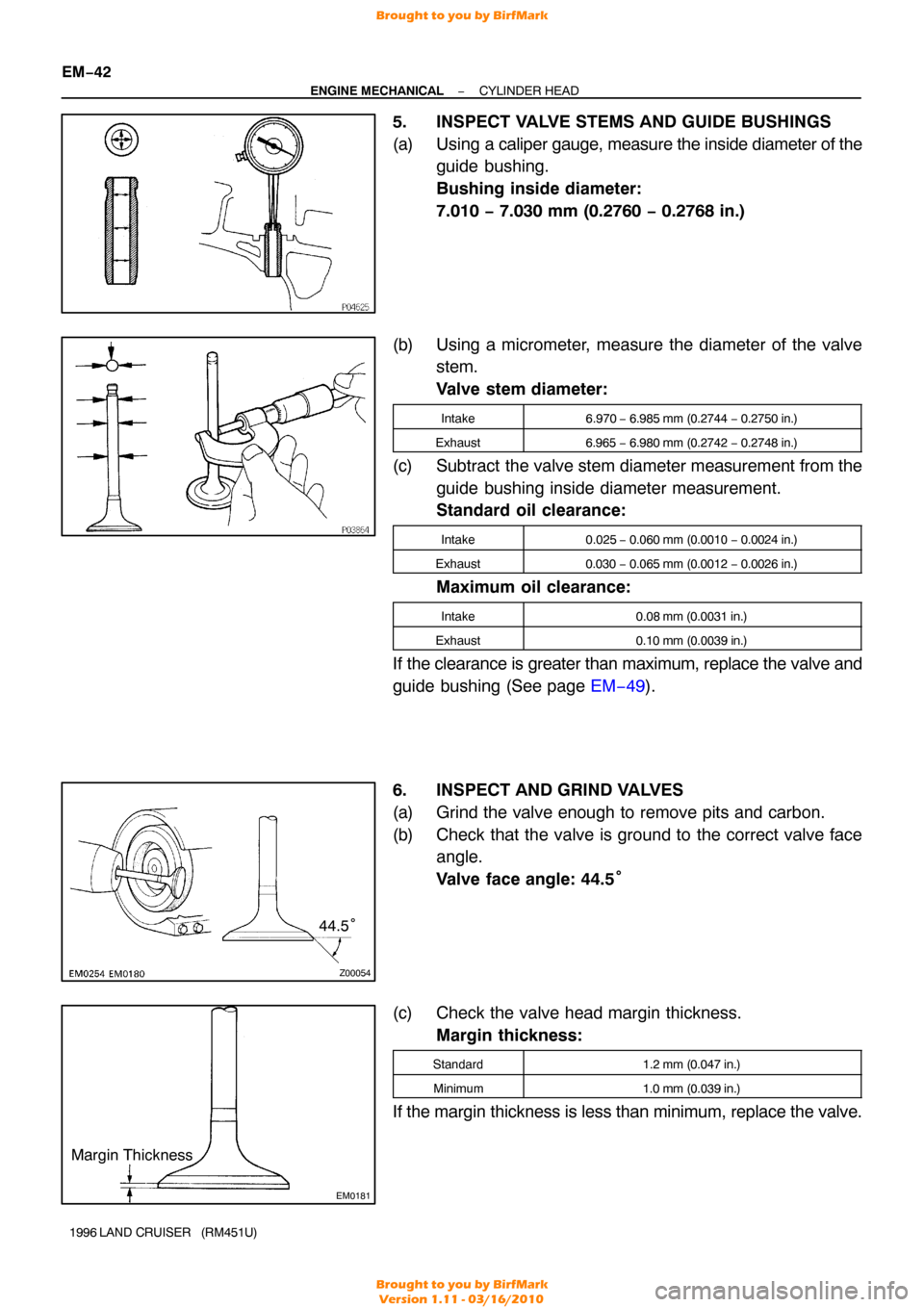
5. INSPECT VALVE STEMS AND GUIDE BUSHINGS
(a) Using a cali per gauge, measure the inside diameter of the
guide bushing.
Bushing inside diameter:
7.010 − 7.030 mm (0.2760 − 0.2768 in.)
(b) Using a micrometer, measure the diameter of the valve stem.
Valve stem diameter:
Intake6.970 − 6.985 mm (0.2744 − 0.2750 in.)
Exhaust6.965 − 6.980 mm (0.2742 − 0.2748 in.)
(c) Subtract the valve stem diameter measurement from the
guide bushing inside diameter measurement.
Standard oil clearance:
Intake0.025 − 0.060 mm (0.0010 − 0.0024 in.)
Exhaust0.030 − 0.065 mm (0.0012 − 0.0026 in.)
Maximum oil clearance:
Intake0.08 mm (0.0031 in.)
Exhaust0.10 mm (0.0039 in.)
If the clearance is greater than maximum, replace the valve and
guide bushing (See page EM−49).
6. INSPECT AND GRIND VALVES
(a) Grind the valve enough to remove pits and carbon.
(b) Check that the valve is ground to the correct valve face angle.
Valve face angle: 44.5°
(c) Check the valve head margin thickness. Margin thickness:
Standard1.2 mm (0.047 in.)
Minimum1.0 mm (0.039 in.)
If the margin thickness is less than minimum, replace the valve.
Brought to you by BirfMark
Brought to you by BirfMark
Version 1.11 - 03/16/2010
Page 1327 of 1399

SS−26
−
SERVICE SPECIFICATIONS TRANSFER
149
Author�: Date�:
1996 LAND CRUISER (RM451U)
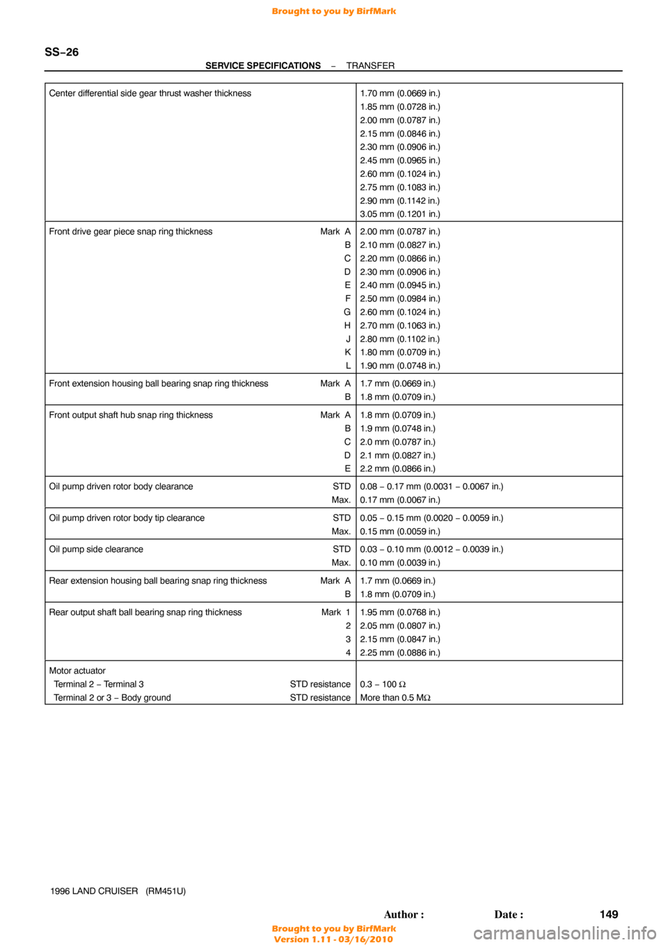
Center differential side gear thrust washer thickness
1.70 mm (0.0669 in.)
1.85 mm (0.0728 in.)
2.00 mm (0.0787 in.)
2.15 mm (0.0846 in.)
2.30 mm (0.0906 in.)
2.45 mm (0.0965 in.)
2.60 mm (0.1024 in.)
2.75 mm (0.1083 in.)
2.90 mm (0.1142 in.)
3.05 mm (0.1201 in.)
Front drive gear piece snap ring thickness
Mark A
B
C
D E
F
G H J
K
L2.00 mm (0.0787 in.)
2.10 mm (0.0827 in.)
2.20 mm (0.0866 in.)
2.30 mm (0.0906 in.)
2.40 mm (0.0945 in.)
2.50 mm (0.0984 in.)
2.60 mm (0.1024 in.)
2.70 mm (0.1063 in.)
2.80 mm (0.1102 in.)
1.80 mm (0.0709 in.)
1.90 mm (0.0748 in.)
Front extension housing ball bearing snap ring thickness Mark A
B1.7 mm (0.0669 in.)
1.8 mm (0.0709 in.)
Front output shaft hub snap ring thickness Mark A
B
C
D E1.8 mm (0.0709 in.)
1.9 mm (0.0748 in.)
2.0 mm (0.0787 in.)
2.1 mm (0.0827 in.)
2.2 mm (0.0866 in.)
Oil pump driven rotor body clearance STD
Max.0.08 − 0.17 mm (0.0031 − 0.0067 in.)
0.17 mm (0.0067 in.)
Oil pump driven rotor body tip clearance STD
Max.0.05 − 0.15 mm (0.0020 − 0.0059 in.)
0.15 mm (0.0059 in.)
Oil pump side clearance STD
Max.0.03 − 0.10 mm (0.0012 − 0.0039 in.)
0.10 mm (0.0039 in.)
Rear extension housing ball bearing snap ring thickness Mark A
B1.7 mm (0.0669 in.)
1.8 mm (0.0709 in.)
Rear output shaft ball bearing snap ring thickness Mark 1
2
3
41.95 mm (0.0768 in.)
2.05 mm (0.0807 in.)
2.15 mm (0.0847 in.)
2.25 mm (0.0886 in.)
Motor actuator
Terminal 2 − Terminal 3 STD resistance
Terminal 2 or 3 − Body ground STD resistance
0.3 − 100 Ω
More than 0.5 MΩ
Brought to you by BirfMark
Brought to you by BirfMark
Version 1.11 - 03/16/2010