Page 1367 of 1399
Z18976
B
Z18977
C
TR−6
−
TRANSFER TRANSFER ASSEMBLY
1996 LAND CRUISER (RM451U)
11. REMOVE RETAINER FROM REAR CASE
Remove the 5 bolts and retainer.
Torque: 39 N·m (400 kgf·cm, 28 ft·lbf)
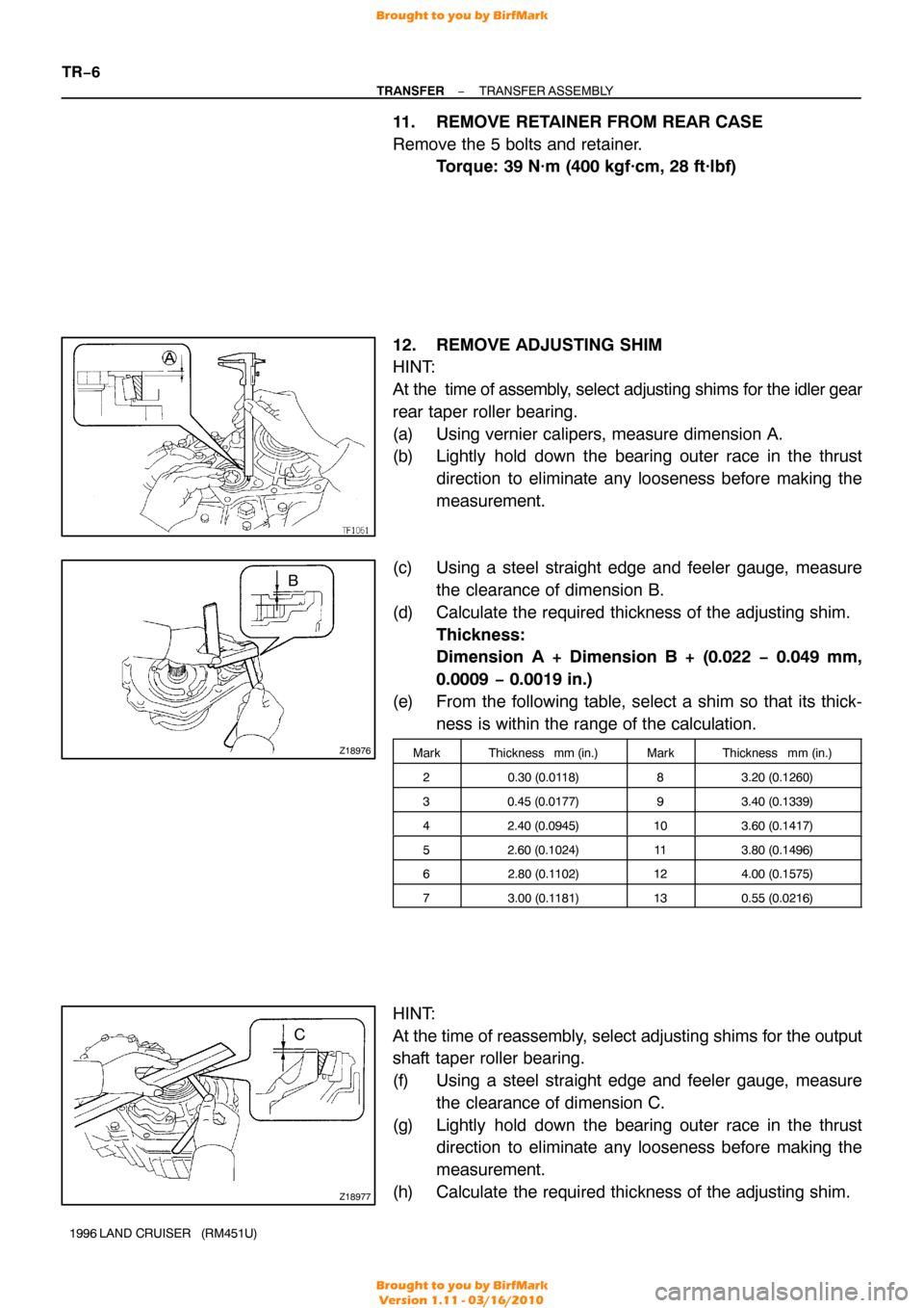
12. REMOVE ADJUSTING SHIM
HINT:
At the time of assembly, select adjusting shims for the idler gear
rear taper roller bearing.
(a) Using vernier calipers, measure dimension A.
(b) Lightly hold down the bearing outer race in the thrust direction to eliminate any looseness before making the
measurement.
(c) Using a steel straight edge and feeler gauge, measure the clearance of dimension B.
(d) Calculate the required thickness of the adjusting shim. Thickness:
Dimension A + Dimension B + (0.022 − 0.049 mm,
0.0009 − 0.0019 in.)
(e) From the following table, select a shim so that its thick- ness is within the range of the calculation.
MarkThickness mm (in.)MarkThickness mm (in.)
20.30 (0.0118)83.20 (0.1260)
30.45 (0.0177)93.40 (0.1339)
42.40 (0.0945)103.60 (0.1417)
52.60 (0.1024)113.80 (0.1496)
62.80 (0.1 102)124.00 (0.1575)
73.00 (0.1181)130.55 (0.0216)
HINT:
At the time of reassembly, select adjusting shims for the output
shaft taper roller bearing.
(f) Using a steel straight edge and feeler gauge, measure
the clearance of dimension C.
(g) Lightly hold down the bearing outer race in the thrust direction to eliminate any looseness before making the
measurement.
(h) Calculate the required thickness of the adjusting shim.
Brought to you by BirfMark
Brought to you by BirfMark
Version 1.11 - 03/16/2010
Page 1368 of 1399
Q07126
FIPG
Q08404
FIPG
A
−
TRANSFER TRANSFER ASSEMBLY
TR−7
1996 LAND CRUISER (RM451U)
Thickness:
Dimension C + (0. 014 − 0.039 mm, 0.0006 − 0.0015 in.)
(i) From the following table, select a shim so that its thick-
ness is within the range of the calculation.
MarkThickness mm (in.)MarkThickness mm (in.)
B0.30 (0.0118)H1.80 (0.0709)
C0.45 (0.0177)J2.00 (0.0787)
D1.00 (0.0394)K2.20 (0.0866)
E1.20 (0.0472)L2.40 (0.0945)
F1.40 (0.0551)M2.60 (0.1024)
G1.60 (0.0630)N0.55 (0.0216)
13. REMOVE OIL STRAINER FROM REAR CASE
Remove the 2 set bolts and oil strainer.Torque: 4.9 N·m (50 kgf·cm, 43 in.·lbf)
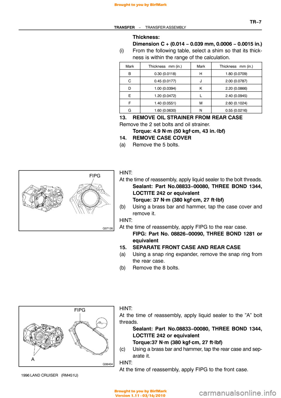
14. REMOVE CASE COVER
(a) Remove the 5 bolts.
HINT:
At the time of reassembly, apply liquid sealer to the bolt threads.
Sealant: Part No.08833−00080, THREE BOND 1344,
LOCTITE 242 or equivalent
Torque: 37 N·m (380 kgf·cm, 27 ft·lbf)
(b) Using a brass bar and hammer, tap the case cover and remove it.
HINT:
At the time of reassembly, apply FIPG to the rear case. FIPG: Part No. 08826−00090, THREE BOND 1281 or
equivalent
15. SEPARATE FRONT CASE AND REAR CASE
(a) Using a snap ring expander, remove the snap ring from the rear case.
(b) Remove the 8 bolts.
HINT:
At the time of reassembly, apply liquid sealer to the ”A” bolt
threads. Sealant: Part No.08833 −00080, THREE BOND 1344,
LOCTITE 242 or equivalent
Torque:37 N·m (380 kgf·cm, 27 ft·lbf)
(c) Using a brass bar and hammer, tap the rear case and sep-
arate it.
HINT:
At the time of reassembly, apply FIPG to the front case.
Brought to you by BirfMark
Brought to you by BirfMark
Version 1.11 - 03/16/2010
Page 1369 of 1399
TF0854
TF0986
TF0857
Q07130
RemovalInstallation
Socket Wrench Socket Wrench
TR−8
−
TRANSFER TRANSFER ASSEMBLY
1996 LAND CRUISER (RM451U)
FIPG: Part No. 08826−00090, THREE BOND 1281 or
equivalent
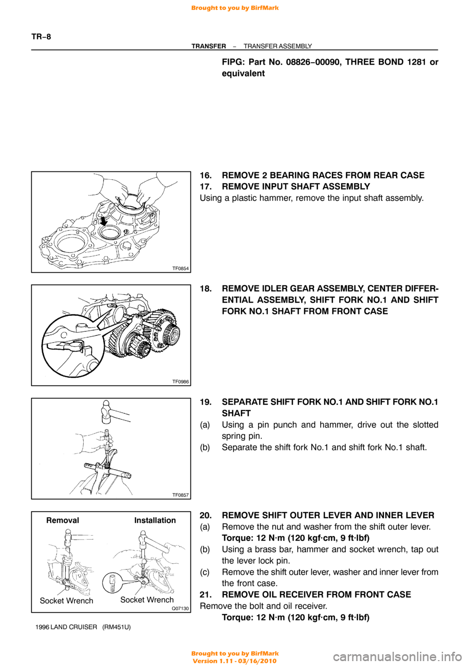
16. REMOVE 2 BEARING RACES FROM REAR CASE
17. REMOVE INPUT SHAFT ASSEMBLY
Using a plastic hammer, remove the input shaft assembly.
18. REMOVE IDLER GEAR ASSEMBLY, CENTER DIFFER-
ENTIAL ASSEMBLY, SHIFT FORK NO.1 AND SHIFT
FORK NO.1 SHAFT FROM FRONT CASE
19. SEPARATE SHIFT FORK NO.1 AND SHIFT FORK NO.1 SHAFT
(a) Using a pin punch and hammer, drive out the slotted spring pin.
(b) Separate the shift fork No.1 and shift fork No.1 shaft.
20. REMOVE SHIFT OUTER LEVER AND INNER LEVER
(a) Remove the nut and washer from the shift outer lever. Torque: 12 N·m (120 kgf·cm, 9 ft·lbf)
(b) Using a brass bar, hammer and socket wrench, tap out the lever lock pin.
(c) Remove the shift outer lever, washer and inner lever from
the front case.
21. REMOVE OIL RECEIVER FROM FRONT CASE
Remove the bolt and oil receiver. Torque: 12 N·m (120 kgf·cm, 9 ft·lbf)
Brought to you by BirfMark
Brought to you by BirfMark
Version 1.11 - 03/16/2010
Page 1383 of 1399
TF0920
Q00534
SST
Q00547
SST
Q00549
TR−22
−
TRANSFER CENTER DIFFERENTIAL
1996 LAND CRUISER (RM451U) 1.85 (0.0728)
2.60 (0.1024)
2.00 (0.0787)2.75 (0.1083)
2.15 (0.0846)2.90 (0.1
142)
2.30 (0.0906)3.05 (0.1201)
(d) In the same way, measure the rear case backlash.
4. INSTALL STRAIGHT PIN TO PINION SHAFT
5. INSTALL REAR SIDE GEAR AND THRUST WASHER
6. INSTALL DIFFERENTIAL REAR CASE
Install the differential rear case and 12 set bolts.
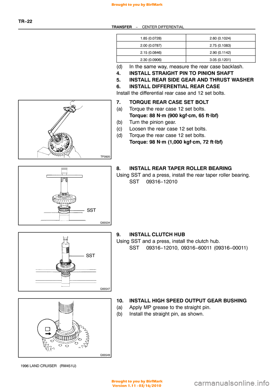
7. TORQUE REAR CASE SET BOLT
(a) Torque the rear case 12 set bolts.
Torque: 88 N·m (900 kgf·cm, 65 ft·lbf)
(b) Turn the pinion gear.
(c) Loosen the rear case 12 set bolts.
(d) Torque the rear case 12 set bolts. Torque: 98 N·m (1,000 kgf·cm, 72 ft·lbf)
8. INSTALL REAR TAPER ROLLER BEARING
Using SST and a press, install the rear taper roller bearing. SST 09316−12010
9. INSTALL CLUTCH HUB
Using SST and a press, install the clutch hub. SST 09316−12010, 09316 −60011 (09316−00011)
10. INSTALL HIGH SPEED OUTPUT GEAR BUSHING
(a) Apply MP grease to the straight pin.
(b) Install the straight pin, as shown.
Brought to you by BirfMark
Brought to you by BirfMark
Version 1.11 - 03/16/2010
Page 1395 of 1399
TF0969
SST
TF0958
Q07138
Q02549
Q08384
TR−34
−
TRANSFER REAR EXTENSION HOUSING
1996 LAND CRUISER (RM451U)
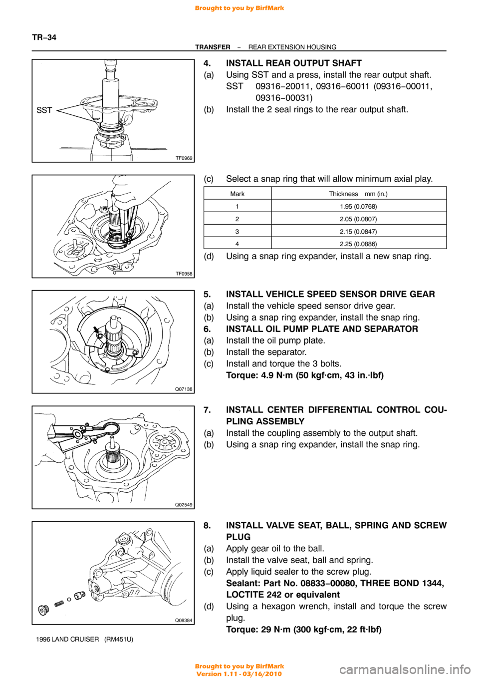
4. INSTALL REAR OUTPUT SHAFT
(a) Using SST and a press, install the rear output shaft.
SST 09316−20011, 09316 −60011 (09316−00011,
09316 −00031)
(b) Install the 2 seal rings to the rear output shaft.
(c) Select a snap ring that will allow minimum axial play.
MarkThickness mm (in.)
11.95 (0.0768)
22.05 (0.0807)
32.15 (0.0847)
42.25 (0.0886)
(d) Using a snap ring expander, install a new snap ring.
5. INSTALL VEHICLE SPEED SENSOR DRIVE GEAR
(a) Install the vehicle speed sensor drive gear.
(b) Using a snap ring expander, install the snap ring.
6. INSTALL OIL PUMP PLATE AND SEPARATOR
(a) Install the oil pump plate.
(b) Install the separator.
(c) Install and torque the 3 bolts. Torque: 4.9 N·m (50 kgf·cm, 43 in.·lbf)
7. INSTALL CENTER DIFFERENTIAL CONTROL COU- PLING ASSEMBLY
(a) Install the coupling assembly to the output shaft.
(b) Using a snap ring expander, install the snap ring.
8. INSTALL VALVE SEAT, BALL, SPRING AND SCREW PLUG
(a) Apply gear oil to the ball.
(b) Install the valve seat, ball and spring.
(c) Apply liquid sealer to the screw plug.
Sealant: Part No. 08833−00080, THREE BOND 1344,
LOCTITE 242 or equivalent
(d) Using a hexagon wrench, install and torque the screw plug.
Torque: 29 N·m (300 kgf·cm, 22 ft·lbf)
Brought to you by BirfMark
Brought to you by BirfMark
Version 1.11 - 03/16/2010
Page 1396 of 1399
TF0977
Q00529
−
TRANSFER REAR EXTENSION HOUSING
TR−35
1996 LAND CRUISER (RM451U)
9. INSTALL DRIVEN ROTOR
(a) Apply gear oil to the driven rotor.
(b) Install the driven rotor.
10. INSTALL DRIVE ROTOR
(a) Apply gear oil to the drive rotor.
(b) Install the drive rotor.
HINT:
Align the alignment marks.
11. INSTALL OIL PUMP COVER
(a) Install the oil pump cover.
(b) Using a torx socket wrench (T30), install and torque the
3 screws.
Torque: 4.9 N·m (50 kgf·cm, 43 in.·lbf)
NOTICE:
Align the oil hole of the rear extension housing and oil
groove end of the oil pump cover.
12. INSTALL OIL PUMP DRIVE SHAFT
Brought to you by BirfMark
Brought to you by BirfMark
Version 1.11 - 03/16/2010