Page 1295 of 1399
SR−42
−
STEERING POWER STEERING GEAR
1996 LAND CRUISER (RM451U)
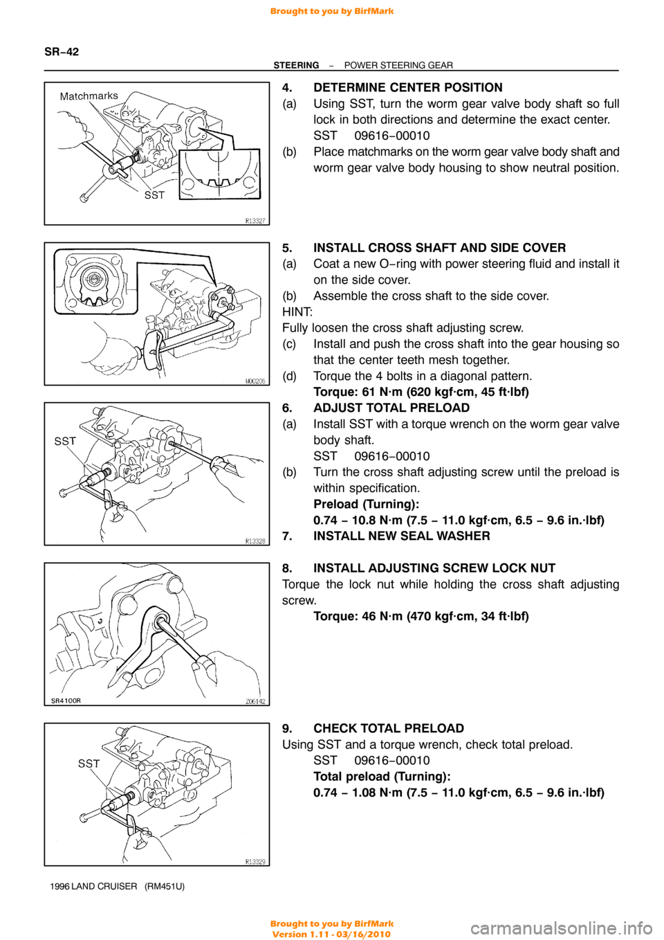
4. DETERMINE CENTER POSITION
(a) Using SST, turn the worm gear valve body shaft so full
lock in both directions and determine the exact center.
SST 09616−00010
(b) Place matchmarks on the worm gear valve body shaft and
worm gear valve body housing to show neutral position.
5. INSTALL CROSS SHAFT AND SIDE COVER
(a) Coat a new O −ring with power steering fluid and install it
on the side cover.
(b) Assemble the cross shaft to the side cover.
HINT:
Fully loosen the cross shaft adjusting screw.
(c) Install and push the cross shaft into the gear housing so that the center teeth mesh together.
(d) Torque the 4 bolts in a diagonal pattern. Torque: 61 N·m (620 kgf·cm, 45 ft·lbf)
6. ADJUST TOTAL PRELOAD
(a) Install SST with a torque wrench on the worm gear valve body shaft.
SST 09616−00010
(b) Turn the cross shaft adjusting screw until the preload is
within specification.
Preload (Turning):
0.74 − 10.8 N·m (7.5 − 11.0 kgf·cm, 6.5 − 9.6 in.·lbf)
7. INSTALL NEW SEAL WASHER
8. INSTALL ADJUSTING SCREW LOCK NUT
Torque the lock nut while holding the cross shaft adjusting
screw. Torque: 46 N·m (470 kgf·cm, 34 ft·lbf)
9. CHECK TOTAL PRELOAD
Using SST and a torque wrench, check total preload. SST 09616−00010
Total preload (Turning):
0.74 − 1.08 N·m (7.5 − 11.0 kgf·cm, 6.5 − 9.6 in.·lbf)
Brought to you by BirfMark
Brought to you by BirfMark
Version 1.11 - 03/16/2010
Page 1296 of 1399
SR16Q−01
SR2922
Alignment Marks
−
STEERING POWER STEERING GEAR
SR−43
1996 LAND CRUISER (RM451U)
INSTALLATION
1. INSTALL PS GEAR ASSEMBLY
Torque the 4 installation bolts and nuts.
Torque: 142 N·m (1,450 kgf·cm, 105 ft·lbf)
2. CONNECT SLIDING YOKE SUB−ASSEMBLY (See page SR−19 )
3. CONNECT PRESSURE FEED AND RETURN TUBES
Using SST, connect the pressure feed and return tubes. SST 09631−22020
Torque: 36 N·m (365 kgf·cm, 26 ft·lbf)
HINT:
�Use a torque wrench with a fulcrum length of 300 mm
(11.81 in.).
�This torque value is effective in case that SST is parallel
to a torque wrench.
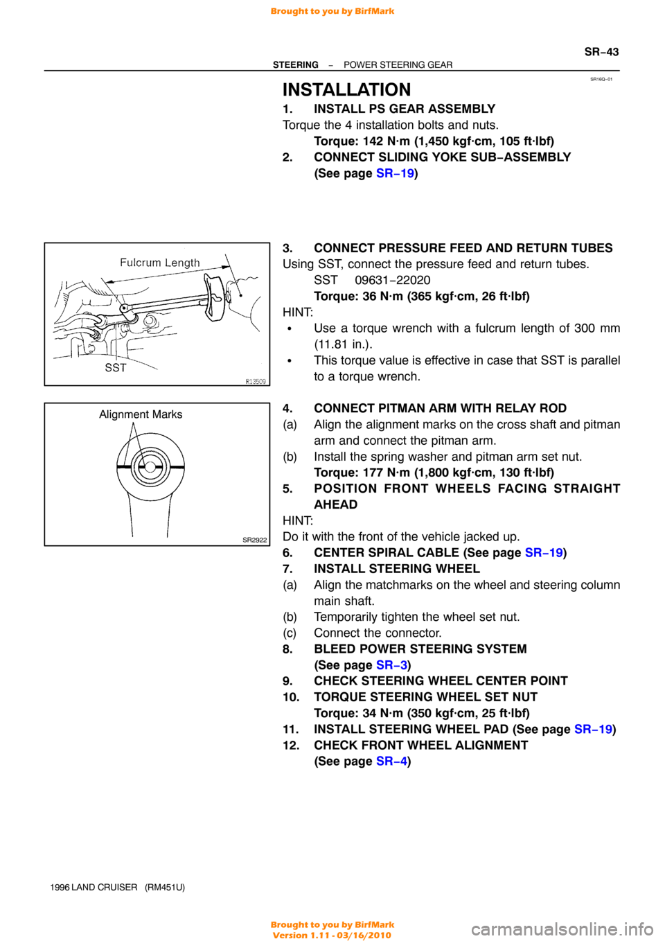
4. CONNECT PITMAN ARM WITH RELAY ROD
(a) Align the alignment marks on the cross shaft and pitman arm and connect the pitman arm.
(b) Install the spring washer and pitman arm set nut. Torque: 177 N·m (1,800 kgf·cm, 130 ft·lbf)
5. POSITION FRONT WHEELS FACING STRAIGHT AHEAD
HINT:
Do it with the front of the vehicle jacked up.
6. CENTER SPIRAL CABLE (See page SR−19 )
7. INSTALL STEERING WHEEL
(a) Align the matchmarks on the wheel and steering column main shaft.
(b) Temporarily tighten the wheel set nut.
(c) Connect the connector.
8. BLEED POWER STEERING SYSTEM
(See page SR−3 )
9. CHECK STEERING WHEEL CENTER POINT
10. TORQUE STEERING WHEEL SET NUT
Torque: 34 N·m (350 kgf·cm, 25 ft·lbf)
11. INSTALL STEERING WHEEL PAD (See page SR−19)
12. CHECK FRONT WHEEL ALIGNMENT (See page SR−4 )
Brought to you by BirfMark
Brought to you by BirfMark
Version 1.11 - 03/16/2010
Page 1300 of 1399
SR16T−01
−
STEERING STEERING LINKAGE
SR−47
1996 LAND CRUISER (RM451U)
INSTALLATION
HINT:
When connecting the ball stud to the arm or rod, remove the
grease on the joint surfaces.
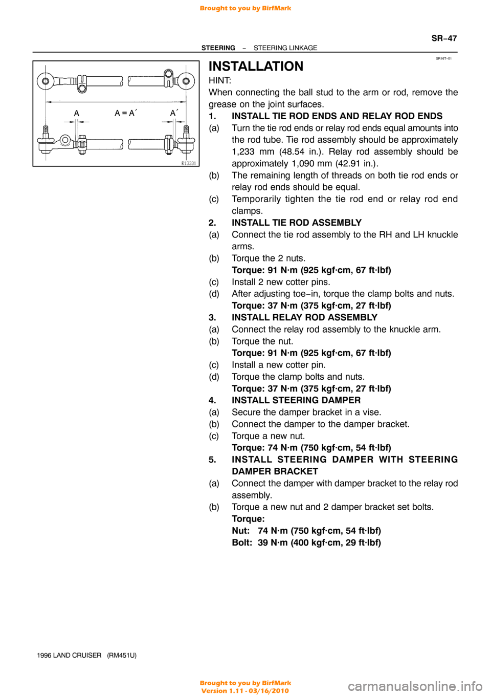
1. INSTALL TIE ROD ENDS AND RELAY ROD ENDS
(a) Turn the tie rod ends or relay rod ends equal amounts into
the rod tube. Tie rod assembly should be approximately
1,233 mm (48.54 in.). Relay rod assembly should be
approximately 1,090 mm (42.91 in.).
(b) The remaining length of threads on both tie rod ends or relay rod ends should be equal.
(c) Temporarily tighten the tie rod end or relay rod end clamps.
2. INSTALL TIE ROD ASSEMBLY
(a) Connect the tie rod assembly to the RH and LH knuckle arms.
(b) Torque the 2 nuts. Torque: 91 N·m (925 kgf·cm, 67 ft·lbf)
(c) Install 2 new cotter pins.
(d) After adjusting toe−in, torque the clamp bolts and nuts. Torque: 37 N·m (375 kgf·cm, 27 ft·lbf)
3. INSTALL RELAY ROD ASSEMBLY
(a) Connect the relay rod assembly to the knuckle arm.
(b) Torque the nut. Torque: 91 N·m (925 kgf·cm, 67 ft·lbf)
(c) Install a new cotter pin.
(d) Torque the clamp bolts and nuts. Torque: 37 N·m (375 kgf·cm, 27 ft·lbf)
4. INSTALL STEERING DAMPER
(a) Secure the damper bracket in a vise.
(b) Connect the damper to the damper bracket.
(c) Torque a new nut. Torque: 74 N·m (750 kgf·cm, 54 ft·lbf)
5. INSTALL STEERING DAMPER WITH STEERING DAMPER BRACKET
(a) Connect the damper with damper bracket to the relay rod
assembly.
(b) Torque a new nut and 2 damper bracket set bolts.
Torque:
Nut: 74 N·m (750 kgf·cm, 54 ft·lbf)
Bolt: 39 N·m (400 kgf·cm, 29 ft·lbf)
Brought to you by BirfMark
Brought to you by BirfMark
Version 1.11 - 03/16/2010
Page 1301 of 1399
SR2922
Alignment Marks
SR−48
−
STEERING STEERING LINKAGE
1996 LAND CRUISER (RM451U)
6. INSTALL PITMAN ARM
(a) Align the alignment marks on the pitman arm and the
cross shaft, and install the spring washer and set nut.
Torque: 177 N·m (1,800 kgf·cm, 130 ft·lbf)
(b) Connect the pitman arm to the relay rod assembly.
(c) Torque the nut. Torque: 91 N·m (925 kgf·cm, 67 ft·lbf)
(d) Install a new cotter pin.
7. INSTALL ENGINE UNDER COVER
Tighten the 4 bolts.
8. CHECK FRONT WHEEL ALIGNMENT (See page SA−4 )
Brought to you by BirfMark
Brought to you by BirfMark
Version 1.11 - 03/16/2010
Page 1303 of 1399
SS00G−01
V00079
ClassDiameter
mm Pitch
mm Specified torque
Hexagon head bolt
Hexagon flange bolt
N·m kgf·cm ft·lbf N·m kgf·cm
ft·lbf
in.·lbf
in.·lbf
in.·lbf in.·lbf
in.·lbf
in.·lbf
SS−2
−
SERVICE SPECIFICATIONS STANDARD BOLT
1996 LAND CRUISER (RM451U)
SPECIFIED TORQUE FOR STANDARD BOLTS
Brought to you by BirfMark
Brought to you by BirfMark
Version 1.11 - 03/16/2010
Page 1304 of 1399
SS1EN−01
−
SERVICE SPECIFICATIONS MAINTENANCE
SS−3
126
Author�: Date�:
1996 LAND CRUISER (RM451U)
MAINTENANCE
TORQUE SPECIFICATION
Part tightenedN·mkgf·cmft·lbf
Front seat mounting bolt3940029
Brought to you by BirfMark
Brought to you by BirfMark
Version 1.11 - 03/16/2010
Page 1308 of 1399
SS1EP−01
−
SERVICE SPECIFICATIONS ENGINE MECHANICAL
SS−7
1996 LAND CRUISER (RM451U)
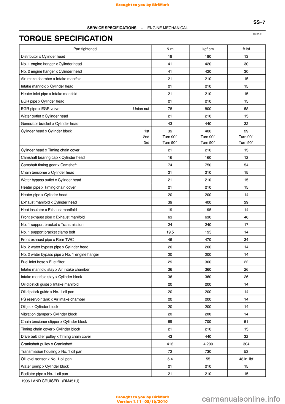
TORQUE SPECIFICATION
Part tightenedN·mkgf·cmft·lbf
Distributor x Cylinder head1818013
No. 1 engine hanger x Cylinder head4142030
No. 2 engine hanger x Cylinder head4142030
Air intake chamber x Intake manifold2121015
Intake manifold x Cylinder head2121015
Heater inlet pipe x Intake manifold2121015
EGR pipe x Cylinder head2121015
EGR pipe x EGR valve Union nut7880058
Water outlet x Cylinder head2121015
Generator bracket x Cylinder head4344032
Cylinder head x Cylinder block 1st
2nd 3rd39
Turn 90°
Turn 90°400
Turn 90°
Turn 90°29
Turn 90°
Turn 90°
Cylinder head x Timing chain cover2121015
Camshaft bearing cap x Cylinder head1616012
Camshaft timing gear x Camshaft7475054
Chain tensioner x Cylinder head2121015
Water bypass outlet x Cylinder head2121015
Heater pipe x Timing chain cover2121015
Heater pipe x Cylinder head2020014
Exhaust manifold x Cylinder head3940029
Heat insulator x Exhaust manifold1919514
Front exhaust pipe x Exhaust manifold6363046
No. 1 support bracket x Transmission2424017
No. 1 support bracket clamp bolt19.519514
Front exhaust pipe x Rear TWC4647034
No. 2 water bypass pipe x Cylinder head2020014
No. 2 water bypass pipe x No. 1 engine hanger2020014
Fuel inlet hose x Fuel filter2930022
Intake manifold stay x Air intake chamber3636026
Intake manifold stay x Cylinder block3636026
Oil dipstick guide x Intake manifold2020014
Oil dipstick guide x No. 1 oil pan2020014
PS reservoir tank x Air intake chamber2020014
Oil jet x Cylinder block2020014
Vibration damper x Cylinder block2020014
Chain tensioner slipper x Cylinder block6970051
Timing chain cover x Cylinder block2121015
Drive belt idler pulley x Timing chain cover4344032
Crankshaft pulley x Crankshaft4124,200304
Transmission housing x No. 1 oil pan7273053
Oil level sensor x No. 1 oil pan5.45548 in.·lbf
Water pump x Cylinder block2121015
Radiator pipe x No. 1 oil pan2121015
Brought to you by BirfMark
Brought to you by BirfMark
Version 1.11 - 03/16/2010
Page 1309 of 1399
SS−8
−
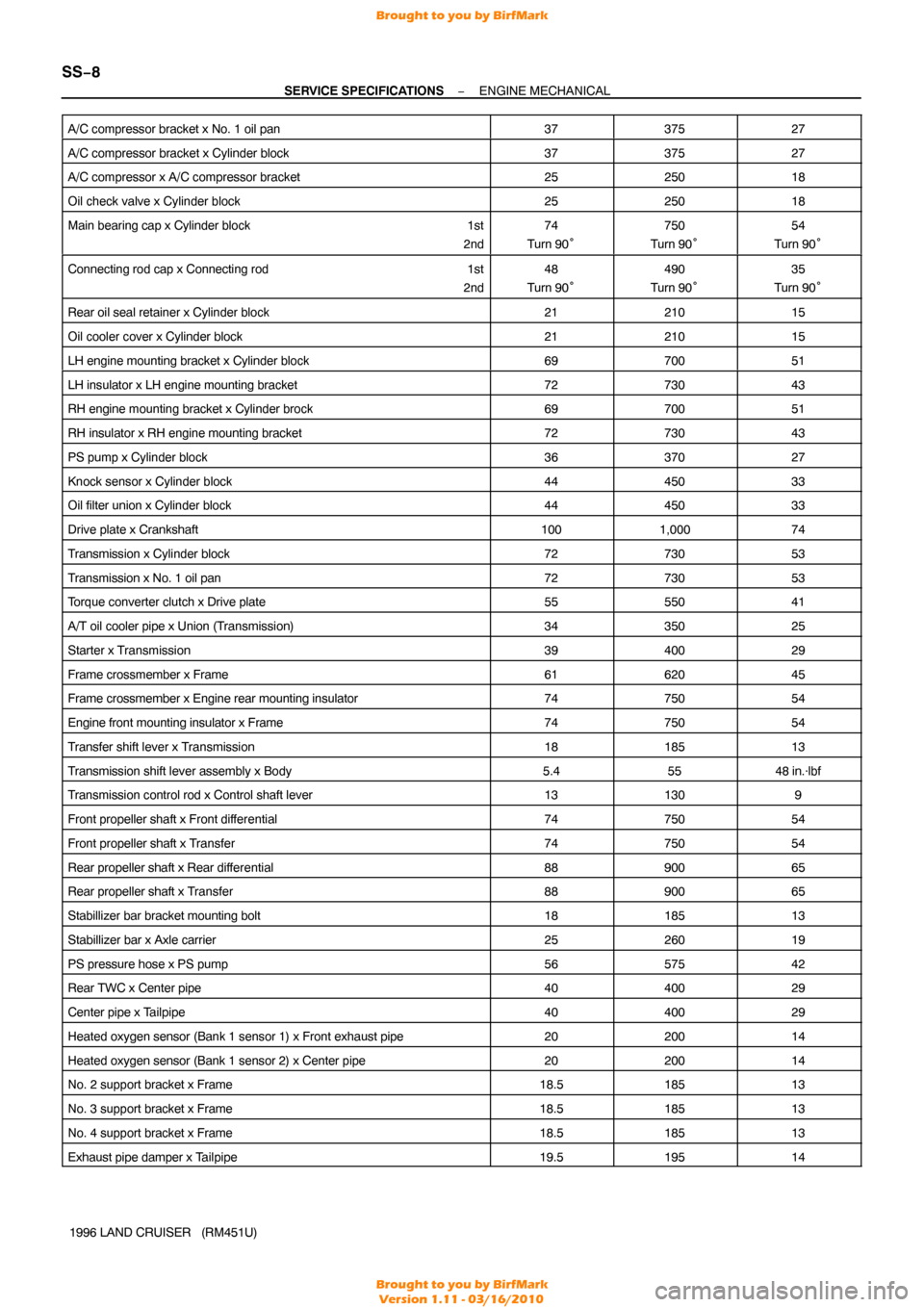
SERVICE SPECIFICATIONS ENGINE MECHANICAL
1996 LAND CRUISER (RM451U)
A/C compressor bracket x No. 1 oil pan
3737527
A/C compressor bracket x Cylinder block3737527
A/C compressor x A/C compressor bracket2525018
Oil check valve x Cylinder block2525018
Main bearing cap x Cylinder block
1st
2nd74
Turn 90°750
Turn 90°54
Turn 90°
Connecting rod cap x Connecting rod 1st
2nd48
Turn 90°490
Turn 90°35
Turn 90°
Rear oil seal retainer x Cylinder block2121015
Oil cooler cover x Cylinder block2121015
LH engine mounting bracket x Cylinder block6970051
LH insulator x LH engine mounting bracket7273043
RH engine mounting bracket x Cylinder brock6970051
RH insulator x RH engine mounting bracket7273043
PS pump x Cylinder block3637027
Knock sensor x Cylinder block4445033
Oil filter union x Cylinder block4445033
Drive plate x Crankshaft1001,00074
Transmission x Cylinder block7273053
Transmission x No. 1 oil pan7273053
Torque converter clutch x Drive plate5555041
A/T oil cooler pipe x Union (Transmission)3435025
Starter x Transmission3940029
Frame crossmember x Frame6162045
Frame crossmember x Engine rear mounting insulator7475054
Engine front mounting insulator x Frame7475054
Transfer shift lever x Transmission1818513
Transmission shift lever assembly x Body5.45548 in.·lbf
Transmission control rod x Control shaft lever131309
Front propeller shaft x Front dif ferential7475054
Front propeller shaft x Transfer7475054
Rear propeller shaft x Rear differential8890065
Rear propeller shaft x Transfer8890065
Stabillizer bar bracket mounting bolt1818513
Stabillizer bar x Axle carrier2526019
PS pressure hose x PS pump5657542
Rear TWC x Center pipe4040029
Center pipe x Tailpipe4040029
Heated oxygen sensor (Bank 1 sensor 1) x Front exhaust pipe2020014
Heated oxygen sensor (Bank 1 sensor 2) x Center pipe2020014
No. 2 support bracket x Frame18.518513
No. 3 support bracket x Frame18.518513
No. 4 support bracket x Frame18.518513
Exhaust pipe damper x Tailpipe19.519514
Brought to you by BirfMark
Brought to you by BirfMark
Version 1.11 - 03/16/2010